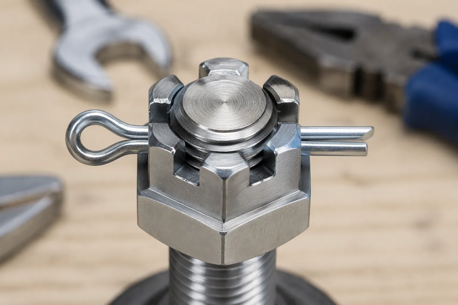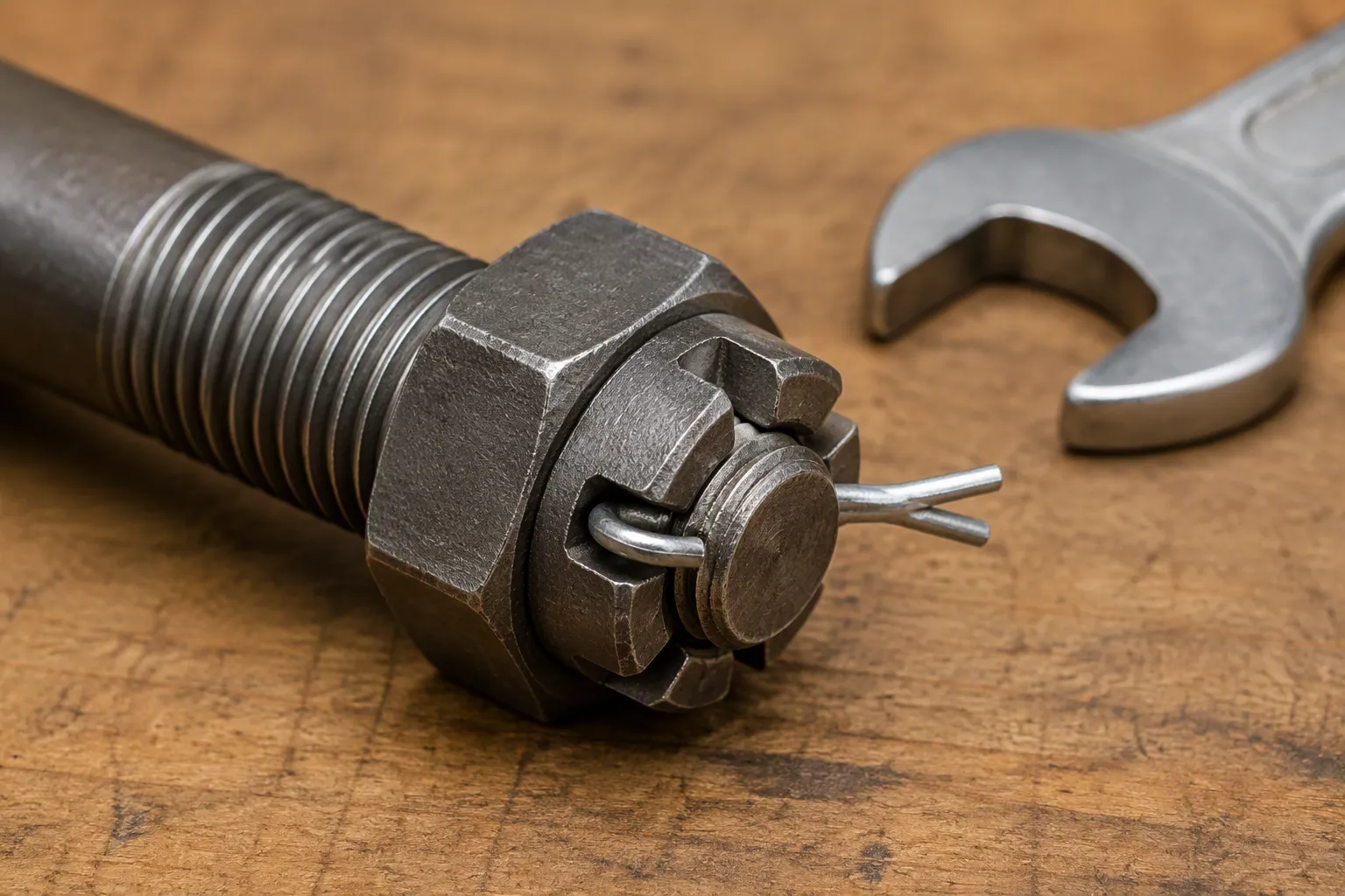
La instalación correcta de los anclajes de cuña es una tarea fundamental. Una encuesta de la ASCE de 2023 reveló que El 34% de los fallos en los pernos de anclaje se debe directamente a errores de instalación. Esto pone de relieve la importancia de una técnica correcta, incluso cuando se utilizan productos de alta calidad como pernos de anclaje personalizados de una empresa de prestigio fabricante de elementos de fijación personalizados. El mercado mundial de estos componentes es considerable y está en crecimiento.

Nota: Un exitoso ancla de cuña La instalación requiere herramientas específicas y equipo de seguridad obligatorio para garantizar tanto la integridad estructural como la seguridad personal.
Antes de la instalación: cómo elegir el anclaje de cuña adecuado

Antes de comenzar a taladrar, el primer paso fundamental es elegir el anclaje adecuado para el trabajo. La seguridad y la durabilidad del elemento de fijación dependen en gran medida de esta decisión inicial. Factores como los requisitos de carga, las condiciones ambientales y el diseño del elemento de fijación influyen a la hora de elegir el anclaje ideal. Tomar una decisión informada Esto es fundamental para una selección e instalación adecuadas.
Comprender el diámetro y la longitud de las anclas
Adaptación del diámetro a los requisitos de carga
El diámetro del anclaje está directamente relacionado con su capacidad de sujeción. Un diámetro mayor suele proporcionar una mayor capacidad de carga a tracción (arrancamiento) y a cizallamiento (de lado a lado). Los ingenieros deben adaptar el diámetro del anclaje a las exigencias específicas de carga de la aplicación. La resistencia del hormigón como material de base también desempeña un papel importante en el rendimiento final del anclaje.
Las capacidades de carga admisibles aumentan en función del diámetro del anclaje, la profundidad de empotramiento y la resistencia del hormigón.
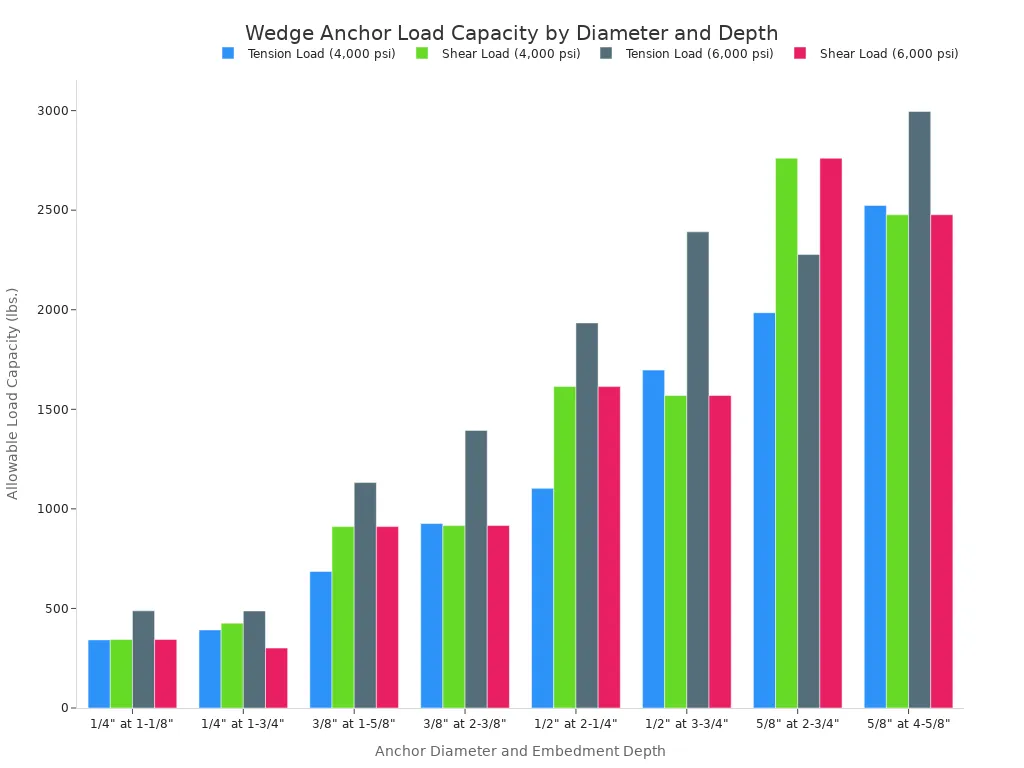
La tabla siguiente ofrece una guía general sobre las cargas admisibles en hormigones de diferentes resistencias.
| Diámetro nominal del anclaje (pulg.) | Profundidad mínima de empotramiento (pulg.) | Resistencia a la compresión del hormigón (psi) | Capacidad de carga de tensión admisible (libras) | Capacidad de carga de corte admisible (libras) |
|---|---|---|---|---|
| 1/4″ | 1-1/8″ | 4,000 | 342 | 344 |
| 3/8″ | 1-5/8″ | 4,000 | 686 | 911 |
| 1/2″ | 2-1/4″ | 4,000 | 1,103 | 1,614 |
| 5/8″ | 2-3/4″ | 4,000 | 1,985 | 2,761 |
| 1/4″ | 1-1/8″ | 6,000 | 488 | 344 |
| 3/8″ | 1-5/8″ | 6,000 | 1,132 | 911 |
| 1/2″ | 2-1/4″ | 6,000 | 1,934 | 1,614 |
| 5/8″ | 2-3/4″ | 6,000 | 2,277 | 2,761 |
Cálculo de la longitud correcta del anclaje
Para garantizar una sujeción adecuada, el anclaje de cuña debe ser lo suficientemente largo como para atravesar el elemento de fijación y alcanzar la profundidad de empotramiento requerida en el hormigón.
Consejo profesional: Utiliza esta sencilla fórmula para calcular el longitud mínima del anclaje:
Espesor del elemento de fijación + profundidad mínima de empotramiento + altura de la tuerca y la arandela = longitud mínima del anclaje
Realizar este cálculo antes de comprar los anclajes evita fallos en la instalación debidos a una longitud insuficiente.
Elegir el material y el recubrimiento adecuados
El material del anclaje determina su resistencia a la corrosión. Elegir el material adecuado es fundamental para garantizar su durabilidad en distintos entornos.
| Tipo de ancla | Resistencia a la corrosión | Condiciones ambientales adecuadas |
|---|---|---|
| Galvanizado | Menos | Lugares secos y cerrados, sin humedad |
| Galvanizado por inmersión en caliente | Medio | Uso en exteriores, entornos húmedos |
| Acero inoxidable 304 | Excelente | Los entornos más corrosivos |
| Acero inoxidable 316 | El mejor | Entornos sumergidos o marinos |
Acero al carbono galvanizado
Estos anclajes están diseñados exclusivamente para aplicaciones en interiores y en condiciones secas. El recubrimiento de zinc ofrece una protección mínima contra la humedad, y la exposición a la misma puede provocar óxido y oxidación.
Galvanizado por inmersión en caliente (HDG)
Gracias a su capa protectora más gruesa, los anclajes HDG son aptos para su uso en exteriores en entornos húmedos o con humedad. Ofrecen una mejora significativa en cuanto a resistencia a la corrosión en comparación con el recubrimiento de zinc estándar.
Acero inoxidable 304
Este material ofrece una excelente resistencia a la corrosión para la mayoría de las aplicaciones en exteriores y en entornos corrosivos. Es una opción fiable para instalaciones a largo plazo en las que la humedad es un factor constante.
Acero inoxidable 316
Para obtener el máximo nivel de protección contra la corrosión, el acero inoxidable 316 es la mejor opción. Es ideal para los entornos más exigentes, incluidas las aplicaciones sumergidas y las zonas expuestas a cloruros, como las sales de deshielo o el aire marino.
Cómo interpretar los tipos de cabezales y las certificaciones
Tuerca y arandela estándar
El tipo más habitual de anclaje de cuña consta de un perno roscado con una tuerca y una arandela. Este diseño está pensado para la fijación permanente y de alta resistencia de elementos como maquinaria, barandillas de seguridad y topes para muelles donde la cabeza del anclaje quedará al descubierto.
Tipos de cabeza plana/avellanada
Para aplicaciones que requieran una superficie lisa y a ras, un anclaje de cabeza plana o avellanada es la opción ideal. Este diseño permite que la cabeza del anclaje quede a ras del material de la estructura, lo que evita el riesgo de tropiezos y aporta un aspecto limpio y acabado. Se suelen utilizar para instalar marcos de puerta y placas metálicas.
Entender las homologaciones de la ICC-ES
Un Homologación de ICC-ES (Servicio de Evaluación del Consejo Internacional de Códigos) El símbolo del ancla es una garantía de calidad y fiabilidad. Indica que el producto se ha sometido a rigurosas pruebas independientes para verificar su rendimiento y su conformidad con las normas de construcción, como la IBC e IRC. Estos informes de evaluación proporcionan a los ingenieros los datos necesarios para especificar anclajes destinados a aplicaciones estructurales, incluido su uso en hormigón agrietado y en zonas sísmicas. La elección de un anclaje con homologación ICC-ES garantiza que cumple con las normas de seguridad y rendimiento establecidas.
Preparación de las herramientas y el equipo de seguridad

El éxito y la seguridad de un proyecto de anclajes de cuña dependen de que se cuente con el el equipo adecuado. Antes de empezar, el instalador debe reunir las herramientas necesarias y el equipo de protección individual (EPI). Esta preparación evita retrasos y minimiza los riesgos de seguridad.
Herramientas imprescindibles para la instalación
Disponer de las herramientas adecuadas agiliza el proceso de instalación y garantiza que el anclaje funcione según sus especificaciones. Cada herramienta cumple una función específica y fundamental.
Taladro percutor
Un taladro percutor es imprescindible para taladrar hormigón. A diferencia de un taladro normal, combina la rotación con una rápida acción de percusión. Este mecanismo pulveriza eficazmente el hormigón, lo que permite que la broca avance. Un taladro normal no tiene la potencia suficiente para esta tarea.
Broca de carburo conforme a la norma ANSI
Los instaladores deben utilizar una broca con punta de carburo diseñada para mampostería. La broca debe cumplir con Normas ANSI B212.15 para garantizar una tolerancia adecuada del orificio. Un orificio taladrado con una broca que no cumpla con los requisitos puede quedar demasiado grande o demasiado pequeño, lo que comprometería la capacidad de sujeción del anclaje.
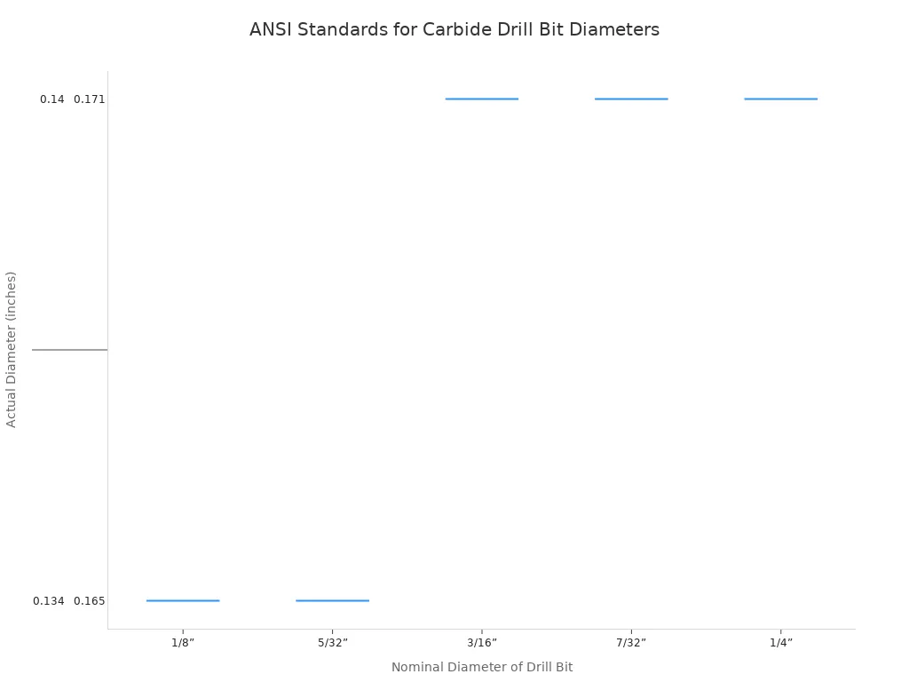
El diámetro del orificio es fundamental. Incluso en el caso de otros tipos de anclajes, como tamaños específicos de Tapcon®, se requieren brocas de diseño especial, ya que sus tolerancias son aún más estrictas que las de las brocas ANSI estándar. La broca debe ajustarse siempre a las especificaciones del fabricante del anclaje.
Llave dinamométrica
Una llave dinamométrica es una herramienta imprescindible para la fase final de apriete. Permite al instalador aplicar la fuerza de giro exacta especificada por el fabricante del anclaje. De este modo se evita tanto un apriete insuficiente —que da lugar a una unión floja— como un apriete excesivo, que puede dañar el hormigón o el propio anclaje.
Cepillo de alambre y aire comprimido/soplador
Estas herramientas se utilizan para limpiar el orificio perforado de todo el polvo y los residuos. Un cepillo de alambre estrecho raspa el polvo de las paredes del orificio. A continuación, una fuente de aire comprimido o un soplador manual elimina todas las partículas sueltas. Es imprescindible que el orificio esté limpio para alcanzar la capacidad de carga nominal del anclaje.
Martillo y llave inglesa
Se necesita un martillo normal para introducir con cuidado el anclaje de cuña en el orificio limpio hasta la profundidad adecuada. Se utiliza una llave básica para apretar a mano la tuerca antes de aplicar el par de apriete definitivo.
Equipos de protección individual (EPI)
La seguridad es primordial cuando se trabaja con hormigón y herramientas eléctricas. Es obligatorio llevar puesto en todo momento el siguiente EPI.
Gafas de seguridad o gafas protectoras
Al taladrar hormigón se generan astillas y polvo fino. Las gafas de seguridad ofrecen una protección esencial contra las lesiones oculares.
Mascarilla antipolvo o respirador
El polvo de hormigón contiene sílice cristalina, que resulta peligrosa si se inhala. Una mascarilla antipolvo o, preferiblemente, un respirador protegen los pulmones del instalador frente a esta sustancia nociva.
Guantes de trabajo
Los guantes de trabajo de alta resistencia protegen las manos de abrasiones y cortes. Además, proporcionan un mejor agarre de las herramientas y los materiales.
Protección auditiva
Un taladro percutor genera mucho ruido. Es imprescindible utilizar orejeras o tapones para los oídos para evitar daños auditivos temporales o permanentes.
Instrucciones de instalación de anclajes de cuña: una guía en 5 pasos
A continuación instrucciones de instalación detalladas Es la parte más importante de la instalación de anclajes de cuña. Estas instrucciones paso a paso detallan el procedimiento correcto, desde la perforación del agujero hasta la colocación del anclaje. Cada uno de los cinco pasos es fundamental para una instalación segura y firme.
Paso 1: Taladra el agujero
El primer paso consiste en realizar un orificio adecuado en el hormigón. Las dimensiones y la calidad de este orificio determinan el rendimiento del anclaje.
Cómo elegir el tamaño adecuado de la broca
El instalador debe utilizar una broca con punta de carburo que cumpla con la norma ANSI. El diámetro de la broca debe coincidir exactamente con el diámetro del anclaje de cuña. Por ejemplo, un anclaje de 1/2″ requiere una broca de 1/2″. El uso de una broca de tamaño incorrecto creará un agujero demasiado holgado o demasiado ajustado, lo que en ambos casos comprometerá la capacidad de sujeción del anclaje.
Cómo determinar la profundidad adecuada del agujero
El orificio debe perforarse hasta una profundidad concreta para que el anclaje alcance la profundidad de empotramiento necesaria. El fabricante especifica una profundidad mínima de empotramiento for each anchor size to achieve its published load values.
| Tamaño del ancla | Empotramiento mínimo |
|---|---|
| 1/4” | 1-1/8” |
| 5/16” | 1-1/8” |
| 3/8” | 1-1/2” |
| 1/2” | 2-1/4” |
| 5/8” | 2-3/4” |
| 3/4” | 3-1/4” |
| 7/8” | 3-7/8” |
| 1” | 4-1/2” |
| 1-1/4” | 5-1/2” |
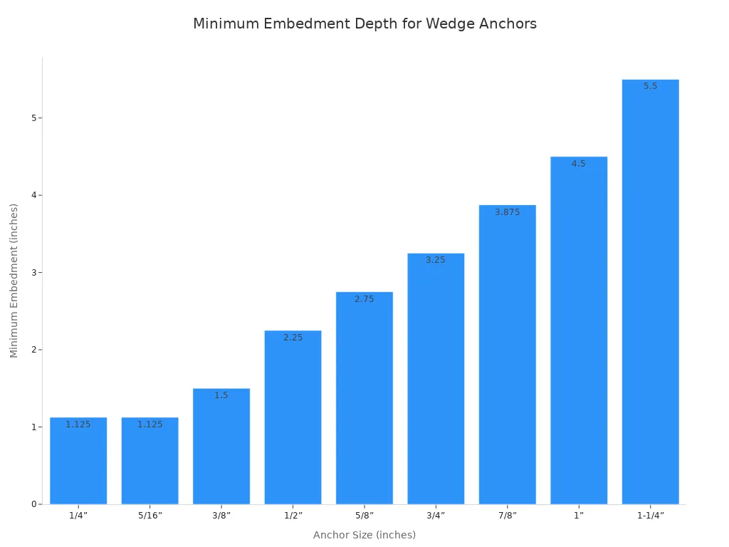
Consejo profesional: Always drill the hole deeper than the minimum embedment. A common rule is to drill the hole at least 1/2″ deeper than the anchor will be embedded. This extra space, or sump, provides a pocket for dust and debris to fall into, ensuring the anchor can be inserted to the correct depth.
Techniques for Drilling a Straight Hole
A perpendicular hole is essential for proper anchor function.
- Use the depth gauge rod on the hammer drill to ensure consistent depth.
- Hold the drill firmly with both hands, keeping it perpendicular to the concrete surface.
- Apply steady, even pressure. Let the hammer drill do the work without forcing it.
- Periodically pull the bit out of the hole as you drill to help clear dust and prevent the bit from binding.
Step 2: Clean the Hole
A clean hole is not optional; it is mandatory for a safe connection. This is one of the most overlooked yet critical parts of the process.
Why Hole Cleaning is Non-Negotiable
Concrete dust and debris left in the hole act as a barrier. This debris prevents the anchor’s expansion clip from making full contact with the solid concrete walls. If dust obstructs the anchor’s full expansion, the wedge anchor can rotate in the hole during tightening, leading to a significant reduction in its holding capacity.
The Wire Brush Method
After drilling, an installer should use a wire brush with a diameter matching the hole size. Insert the brush to the bottom of the hole and twist and scrub vigorously. This action scrapes dust that is compacted against the sides of the hole.
The Compressed Air or Blower Method
Following the brushing, all loose particles must be removed. Use a can of compressed air with an extension nozzle or a manual blower bulb. Place the nozzle at the bottom of the hole and blow outwards. This forces all dust and debris up and out of the hole.
Safety First: OSHA Regulations OSHA standard 1910.242(b) states that compressed air used for cleaning must be regulated to less than 30 psi for safety. This refers to the static pressure when the nozzle is blocked. Installers must use commercially available, safety-compliant nozzles and never modify them, as this can defeat the safety mechanism and create a hazard.
The “Brush and Blow” Combination
The most effective cleaning method is a sequence of brushing and blowing. The professional standard is a “brush, blow, brush, blow” cycle.
- Brush the hole thoroughly.
- Blow the hole out completely.
- Brush the hole a second time to remove any remaining stubborn particles.
- Blow the hole out one final time to ensure it is perfectly clean.
Step 3: Insert the Wedge Anchor
With a clean, properly dimensioned hole, the anchor is ready for placement. This step involves setting the anchor to the correct depth before applying torque.
Driving the Anchor into the Hole
Place the nut on the top of the anchor, leaving it threaded on a few turns to protect the threads. Gently tap the top of the anchor with a hammer. Drive it through the fixture and into the concrete hole until the washer and nut are snug against the surface of the material being fastened.
Setting the Correct Embedment Depth
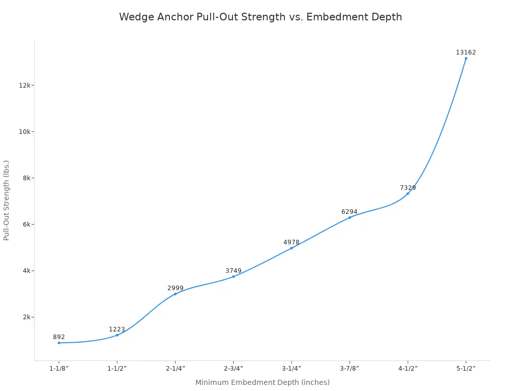
The anchor must be installed to its profundidad mínima de empotramiento to achieve its rated pull-out strength. Deeper embedment generally results in higher holding values. The relationship between embedment and strength is direct and significant.
| Tamaño del ancla | Minimum Embedment Depth | Pull-Out Strength (lbs.) |
|---|---|---|
| 1/4” | 1-1/8” | 877 |
| 5/16” | 1-1/8” | 892 |
| 3/8” | 1-1/2” | 1223 |
| 1/2” | 2-1/4” | 2999 |
| 5/8” | 2-3/4” | 3749 |
| 3/4” | 3-1/4” | 4978 |
| 7/8” | 3-7/8” | 6294 |
| 1” | 4-1/2” | 7329 |
| 1-1/4” | 5-1/2” | 13162 |
To achieve the published holding values, the anchor must be embedded into the concrete at least to this specified depth.
Placing Your Fixture Over the Anchor
Wedge anchors are designed for “through-the-fixture” installation. This means the installer drills the hole through the pre-positioned fixture and into the concrete. The anchor is then inserted through the fixture and into the hole in one continuous motion. This method ensures perfect alignment between the fixture and the anchor.
Step 4: Set the Anchor
After inserting the anchor, the next procedure is to “set” it. This action engages the anchor’s expansion mechanism, creating the initial friction against the concrete that is fundamental to its holding power. This phase prepares the anchor for final tightening.
Hand-Tightening the Nut
Using a standard wrench, an installer should tighten the nut three to four full turns past the hand-tight position. This initial tightening draws the anchor stud upward, removing any slack between the fixture, the anchor, and the concrete. The goal is to make the assembly snug, ensuring all components are in firm contact before applying the final, measured force.
How the Wedging Mechanism Works
The genius of the wedge anchor lies in its simple yet powerful mechanical design. Tightening the nut initiates a sequence of events that locks the anchor into the concrete.
- The installer tightens the nut on the threaded stud.
- This rotational force pulls the entire stud assembly upward, toward the surface.
- As the stud moves up, it forces the expansion clip at the bottom to ride up the anchor’s tapered cone.
- The clip expands outward, becoming tightly wedged between the cone and the walls of the concrete hole. This action generates immense frictional force, which is the source of the anchor’s holding capacity.
Confirming the Anchor is Set
A properly set anchor will feel solid. As the installer hand-tightens the nut, the resistance should increase steadily. The anchor should not spin in the hole. If the entire anchor assembly turns while tightening the nut, it is a clear sign of a problem. This spinning usually indicates an oversized or improperly cleaned hole, which prevents the clip from gripping the concrete. The installer must stop and diagnose the issue before proceeding.
Step 5: Apply Final Torque
Applying the correct final torque is one of the most critical steps in the entire process. This precision measurement ensures the anchor achieves its full, engineered load capacity and creates a secure, long-lasting connection. These final steps in the installation instructions must not be overlooked.
Why Using a Torque Wrench is Critical
A torque wrench is the only tool that can apply a specific, measurable amount of rotational force. Using a standard impact wrench or guessing the tightness by “feel” is a recipe for failure.
- Under-tightening leaves the connection loose. The expansion clip will not generate enough frictional force, severely reducing the anchor’s holding power and allowing the fixture to shift under load.
- Over-tightening is equally dangerous. Excessive force can crack the surrounding concrete, a failure known as cone breakout. It can also stretch the anchor’s steel stud beyond its yield point, permanently damaging the wedge anchor and compromising its integrity.
Professional Standard: A calibrated torque wrench is not optional; it is a mandatory tool for any professional installing mechanical anchors. It is the only way to guarantee the installation meets manufacturer specifications and building code requirements.
Finding the Manufacturer’s Torque Value
Torque values are not universal. They are specified by the manufacturer for each anchor diameter. An installer must always consult the manufacturer’s documentation or the ICC-ES report for the specific product being used. Using the wrong value can lead to the problems described above.
The table below shows a sample of typical installation torque values.
| Diameter (inches) | Length (inches) | Torque (Ft/Lbs) |
|---|---|---|
| 1/4 | 1-3/4 | 5-10 |
| 1/4 | 2-1/4 | 5-10 |
| 1/4 | 3 | 5-10 |
| 1/4 | 3-1/4 | 5-10 |
| 5/16 | 2-3/4 | 5-10 |
Nota: Always verify the required torque for your specific anchor. These values are for illustrative purposes only.
How to Use a Torque Wrench Correctly
Using a click-style torque wrench is a straightforward process.
- Set the Torque: Adjust the handle on the wrench to the manufacturer’s specified torque value (e.g., 10 ft-lbs).
- Apply Force: Place the wrench’s socket over the anchor nut. Apply smooth, steady pressure to the handle in a single, continuous motion. Do not use jerky movements.
- Listen for the Click: Continue applying pressure until the wrench makes an audible “click” and the handle momentarily gives way.
- Stop Immediately: The click signifies that the target torque has been reached. The installer must stop tightening immediately. Applying more force after the click will over-torque the anchor.
The Science of Installing Wedge Anchors: Spacing and Edge Distance
Properly installing wedge anchors involves more than just drilling and tightening. An installer must understand the science behind anchor placement. The distance between anchors and their proximity to a concrete edge are critical factors that directly impact the safety and load-bearing capacity of the entire connection.
Minimum Anchor Spacing Requirements
Why Spacing Matters for Concrete Integrity
Each wedge anchor creates a cone-shaped zone of stress within the concrete as it bears a load. Placing anchors too close together causes these stress cones to overlap. This overlap concentrates force in a small area, which can compromise the concrete’s structural integrity and significantly reduce the holding power of the entire anchor group.
General Rules for Anchor-to-Anchor Distance
A widely accepted guideline is to maintain a minimum spacing of ten anchor diameters between anchors. For example, two 1/2″ anchors should be installed at least 5″ apart.
| Diámetro del anclaje | Minimum Spacing (10x Diameter) |
|---|---|
| 1/4″ | 2-1/2″ |
| 3/8″ | 3-3/4″ |
| 1/2″ | 5″ |
| 5/8″ | 6-1/4″ |
Importante: This is a general rule. An installer must always consult the manufacturer’s specifications, as requirements can vary based on the anchor design, load, and the specified
profundidad mínima de empotramiento.
How Load Affects Spacing
Heavier loads require greater spacing. Increased distance allows the stress from each anchor to be distributed over a larger, non-overlapping area of concrete. For critical applications, an engineer will calculate the precise spacing needed to ensure the concrete can handle the combined forces without failure.
Minimum Edge Distance Requirements
The Risk of Concrete Breakout
Placing an anchor too close to an unsupported edge of a concrete slab or wall is extremely dangerous. The expansion force of the anchor can cause a “blowout” or “breakout,” where a cone-shaped piece of concrete breaks away from the edge. This results in a complete and catastrophic failure of the anchor connection.
Calculating Safe Edge Distance
The expansion anchor industry has established a minimum standard to prevent this failure. A reliable rule of thumb for edge distance is to maintain a distance of at least five anchor diameters from any unsupported edge. Following this guideline helps ensure the anchor is surrounded by enough concrete mass to resist the expansion forces during tightening and the service loads afterward. This distance is just as important as achieving the correct profundidad mínima de empotramiento.
Adjustments for Cracked vs. Uncracked Concrete
Engineers must consider whether the concrete is cracked or uncracked. Designing for uncracked concrete is only permissible if a detailed stress analysis confirms the area will remain free of tensile-induced cracks. For most situations, assuming the concrete is or will be cracked is the safer approach.
Modern fasteners, such as the SD1 concrete wedge anchor, are specifically engineered to perform reliably in both cracked and uncracked concrete conditions. Design methodologies like Strength Design use different strength reduction factors for each condition, evaluating multiple failure modes to create an optimized design. The inclusion of cracked masonry data in anchor testing criteria further shows the industry’s focus on safety. This provides engineers with the necessary data for a secure installation, as a ancla de cuña can be negatively impacted by cracks. The profundidad mínima de empotramiento is a key parameter in these calculations.
Common Mistakes When Installing a Wedge Anchor
Even with the right tools and materials, simple errors during installation can lead to catastrophic failure. An installer must avoid these common pitfalls to ensure a secure and reliable connection. Understanding these mistakes is a key part of properly installing wedge anchors.
Mistake 1: Incorrect Hole Dimensions
The hole is the foundation of the connection. Incorrect dimensions will compromise the entire installation.
The Problem with an Oversized Hole
A hole drilled with a worn or incorrect bit will be too large. This creates a radial gap between the anchor’s expansion clip and the concrete wall. The clip cannot expand enough to create the necessary friction. Studies show this can lead to localized concrete crushing or micro-cracking around the anchor head, which precedes a larger failure. The anchor will spin in the hole and will never achieve its rated load.
The Danger of a Shallow Hole
A hole that is not deep enough prevents the anchor from reaching its specified minimum embedment. This drastically reduces its pull-out strength. For larger anchors (5/8″ and up), installing in a shallow hole can reduce shear force resistance by approximately 20% compared to published values. The anchor’s wedging mechanism will not engage deep enough within the solid base material.
Mistake 2: Inadequate Hole Cleaning
A clean hole is non-negotiable for a safe installation. Many installers underestimate the importance of this step.
Cómo los residuos reducen el poder de retención
Concrete dust left in the hole acts like a layer of fine ball bearings. This debris prevents the expansion clip from making direct, solid contact with the concrete. The clip presses against the dust instead of the hole wall, severely limiting the frictional force the anchor can generate.
The Consequences of a Dirty Hole
When an installer is installing a wedge anchor in a dirty hole, the anchor will often spin during tightening. This is a clear sign that the clip is not gripping. The result is a connection with a dangerously low holding value, making it susceptible to failure under even light loads.
Mistake 3: Improper Torque Application
Applying the correct torque is a precision step. Both too much and too little force will cause the connection to fail.
The Signs of an Over-Torqued Anchor
Over-tightening an anchor with an impact wrench or by “feel” can destroy the connection. The excessive force can cause several types of failure:
- Concrete Cone Failure: The stress exceeds the concrete’s strength, causing a cone-shaped piece of the base material to break away.
- Steel Failure (Tensile): The anchor stud itself fractures, often at its smallest cross-section, leaving part of the anchor stuck in the hole.
- Steel Failure (Shear): The anchor bolt snaps at the surface of the concrete when subjected to extreme side loads.
The Risk of an Under-Torqued Anchor
An under-torqued anchor is a loose anchor. Insufficient tightening means the expansion clip is not fully engaged against the concrete. The connection will have significantly reduced holding power and may loosen further over time, especially when subjected to vibration.
Mistake 4: Hitting Rebar During Drilling
Drilling into reinforced concrete presents a common challenge: hitting steel rebar. This obstruction is not just an inconvenience; it is a critical structural component of the concrete. An installer’s response to hitting rebar determines the safety of the installation and the integrity of the base material. Attempting to force a standard carbide bit through steel is a significant error that can lead to bit failure and potential structural damage.
How to Identify and Handle Rebar Hits
An operator can easily identify a rebar strike through several distinct signs. Recognizing these signals immediately is the first step in proper handling.
- Sudden Stop: The hammer drill will abruptly stop advancing into the concrete, despite the motor running.
- Change in Sound: The grinding noise of drilling concrete will change to a high-pitched metallic ringing or screeching sound.
- Lack of Dust: The creation of concrete dust will cease, as the bit is no longer pulverizing the base material.
Immediate Action: The moment an installer suspects a rebar hit, they must stop drilling immediately. Continuing to apply force will overheat and destroy the carbide tip of the drill bit. It will not cut the rebar and only risks damaging the tool and the structural steel.
Relocating the Hole vs. Specialized Drilling
Once drilling has stopped, the installer has two primary options. The correct choice depends on the project’s engineering requirements and flexibility.
1. Relocate the Hole (Recommended Method) For most applications, the safest and simplest solution is to abandon the obstructed hole and drill a new one. The installer must move the anchor location according to established spacing guidelines. A new hole must be drilled at a sufficient distance from the original hole to avoid overlapping stress zones.
Consejo profesional: A new hole should be located at least two times the embedment depth away from the abandoned hole. This ensures each location maintains its own structural integrity. Always check project specifications for precise requirements.
2. Use a Specialized Rebar-Cutting Bit (Expert Use Only) In rare cases where the anchor location is absolutely fixed, an installer may need to drill through the rebar. This requires a specialized drill bit designed to cut through steel.
| Action | When to Use | Key Consideration |
|---|---|---|
| Relocate Hole | Most situations; flexible fixture placement. | Easiest, safest, and preserves structural integrity. |
| Drill Through Rebar | Fixed anchor points; no other option. | ⚠️ Requires explicit approval from a structural engineer. |
Cutting rebar is a serious structural modification. It can weaken the concrete’s tensile strength and should never be done without an engineer’s direct approval. The engineer will determine if cutting a specific piece of rebar is acceptable for the structure’s overall design. Unauthorized cutting can compromise the safety of the entire concrete element.
A successful wedge anchor installation depends on precision at every stage. An installer can achieve a perfect result by following a final checklist for the installation process:
- Drill a correctly sized and dimensioned hole.
- Clean all dust and debris from the hole.
- Set the anchor to the required embedment depth.
- Apply the specified torque with a calibrated wrench.
The golden rule remains constant: Always follow the manufacturer’s specifications for the specific anchor being used.
Properly installing wedge anchors is the only way to guarantee a safe and reliable connection.
PREGUNTAS FRECUENTES
Can an installer reuse a wedge anchor?
No. An installer must never reuse a ancla de cuña. The removal process damages the expansion clip and can stretch the anchor’s threads. Reusing a compromised anchor creates a significant safety risk and will lead to connection failure.
What happens if an anchor spins in the hole?
Spinning indicates a problem. The hole is likely oversized or contains debris. This prevents the expansion clip from gripping the concrete. The installer must abandon the hole, diagnose the cause, and drill a new hole in a different location.
Is a torque wrench really necessary?
Yes. A torque wrench is mandatory for a safe installation. It is the only tool that ensures the installer applies the precise force required by the manufacturer. Guessing tightness leads to under-torqued or over-torqued anchors, both of which are unsafe.
Can wedge anchors be used in brick or block?
No. Wedge anchors are designed exclusively for solid concrete. The high expansion forces they generate will crack or break weaker base materials like brick, cinder block, or hollow concrete block. An installer should use sleeve anchors for these materials.
How long should an installer wait to install anchors in new concrete?
An installer must wait for new concrete to cure fully. Concrete typically requires a minimum of 28 days to reach its designed compressive strength. Installing an anchor in “green” or uncured concrete will result in a failed connection.
What is the difference between a wedge anchor and a sleeve anchor?
A wedge anchor provides superior holding power in solid concrete through a small, powerful expansion clip. A sleeve anchor uses a larger expansion sleeve, making it suitable for softer or more brittle materials like brick and block where lower stress is required.
Why did the concrete crack around the anchor?
Concrete cracking usually results from two errors:
- The anchor was installed too close to an edge.
- The installer applied excessive torque.
Both mistakes create stress that exceeds the concrete’s strength, causing it to fail.