Selecting the correct anchor bolts is critical for a safe light pole installation. The industry standard specifies hot-dip galvanized, L-type or J-type steel bolts meeting ASTM F1554 Grade 55. Proper anchor bolt sizes depend on the light pole’s height, weight, and environmental loads. A custom fasteners manufacturer often produces these custom fasteners to meet precise engineering requirements.
There is no universal solution for these components. A project’s structural plans dictate the exact specifications for all custom anchor bolts. This ensures the foundation’s integrity and long-term stability.
Fundamentals of Anchor Bolts for Light Poles

Anchor bolts form the critical link between a concrete foundation and the light pole itself. Installers insert these fasteners into wet concrete, using a template to ensure a perfect fit for the pole’s base plate. Their primary function is to secure the pole to the foundation and maintain its stability. A failure in these anchor bolts compromises the entire structure’s integrity. Understanding the different types of anchor bolts, materials, and coatings is essential for a successful project.
Common Anchor Bolt Types
Engineers select from several common designs based on the required holding strength and foundation engineering.
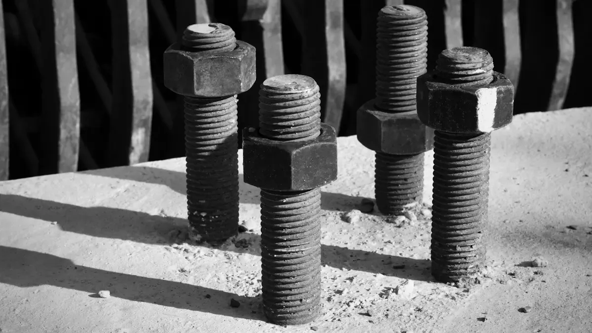
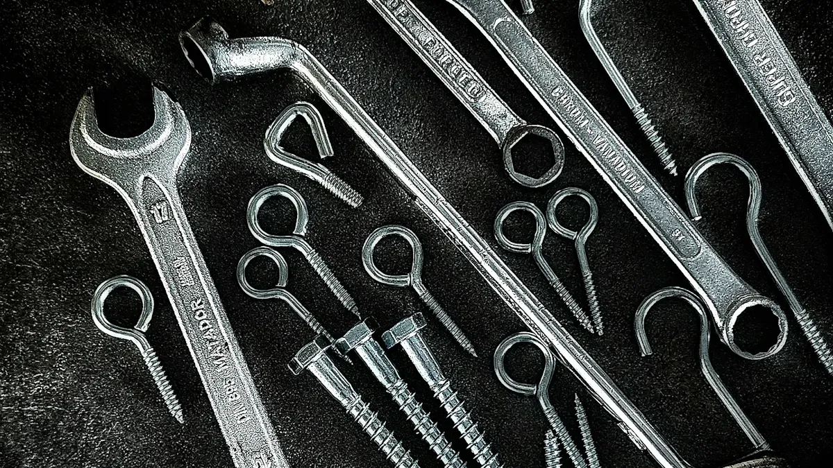
L-Type (Bent-Anchor) Bolts
L-type bolts feature a 90-degree bend at the non-threaded end. This “L” shape provides excellent resistance against pull-out forces once embedded in concrete, making it a very common choice for light pole applications.
J-Type Bolts
Similar to the L-type, the J-type bolt has a curved, hook-shaped end. This hook also provides strong mechanical anchoring within the concrete, resisting tension and shear forces effectively.
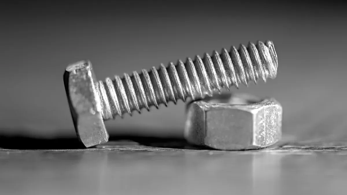
Headed Anchor Bolts with Plate
This configuration uses a straight, headed bolt, often with a steel plate and nut at the embedded end. The plate significantly increases the bearing surface area, offering maximum resistance to pull-out for heavy-duty or high-load scenarios.
Critical Material Specifications: ASTM F1554
The ASTM F1554 specification governs the manufacturing of anchor bolts, ensuring they meet specific chemical and mechanical properties. It is divided into three strength grades.
| Grade | Minimum Yield Strength (ksi) | Tensile Strength Range (ksi) |
|---|---|---|
| 36 | 36 | 58 – 80 |
| 55 | 55 | 75 – 95 |
| 105 | 105 | 125 – 150 |
ASTM F1554 Grade 36
Grade 36 is a low-carbon steel suitable for general-purpose anchoring with lower load demands. It offers good ductility but is less common for structural light pole installations.
ASTM F1554 Grade 55
Industry Standard: Grade 55 is the most specified material for light pole and traffic signal supports. Made from a modified mild steel, it provides an excellent balance of strength and cost-effectiveness. Its use in these applications predates the 1994 F1554 standard, demonstrating its long-standing reliability.
ASTM F1554 Grade 105
Grade 105 is a high-strength, heat-treated alloy steel. Engineers reserve this grade for applications with extreme tensile loads, such as very tall poles or structures in high-wind zones.
The Role of Protective Coatings
A protective coating is vital for preventing corrosion and ensuring the long-term durability of anchor bolts.
Hot-Dip Galvanization (ASTM A153)
Hot-dip galvanization is the most common and effective corrosion protection method. The process creates a durable, metallurgically bonded zinc coating that offers reliable, maintenance-free performance in most outdoor environments.
Stainless Steel Bolts
Project specifications call for stainless steel in highly corrosive areas.
- Environments with salt water or salt-laden air require stainless steel.
- It prevents galvanic corrosion that can occur when dissimilar metals are in contact.
Weathering Steel (A588)
Weathering steel, often specified by its ASTM A588 designation, develops a stable, rust-like patina over time. This outer layer protects the steel from further corrosion and is chosen when a specific aesthetic is desired to match a weathering steel light pole.
How to Select the Correct Anchor Bolts
Selecting the correct anchor bolts is a process driven by engineering principles, not guesswork. Installers must analyze several interconnected factors to ensure the chosen fasteners can support the structure safely for its entire service life. The final selection always comes from the project’s official engineering plans, which synthesize these critical variables into a precise specification.
Key Factors in Bolt Selection
Engineers consider four primary elements when specifying the correct anchor bolt sizes and grades for a project. Each factor contributes to the overall load calculations that the fasteners must withstand.
Pole Specifications
The physical characteristics of the light pole are the starting point. Its height, weight, and material directly impact the forces transferred to the foundation. Taller, heavier poles naturally exert greater loads, requiring stronger, and often larger diameter, anchor bolts to secure them.
Environmental Loads
Environmental forces, especially wind, are a primary concern. Engineers calculate the pole’s resistance to wind using a value called Effective Projected Area (EPA). This calculation accounts for the surface area of the pole plus all attachments like luminaires, brackets, and banners.
Calculating Total EPA Manufacturers use the total EPA and the project site’s maximum wind speed to rate a pole. The process involves these steps:
- Identify all fixtures, brackets, and accessories for the pole.
- Calculate the total EPA using the formula:
(EPA of fixtures × quantity) + (EPA of brackets × quantity) + (EPA of accessories × quantity).- Reference a wind map to determine the maximum wind velocity for the installation area.
- Provide the total EPA and wind velocity to the manufacturer.
- The manufacturer confirms if the selected light pole is suitable or recommends adjustments.
Foundation Design
The concrete foundation is engineered in tandem with the light pole and its fasteners. The foundation’s depth and reinforcement design dictate the required embedment depth of the bolts. Deeper embedment provides greater resistance to pull-out forces, ensuring the entire assembly acts as a single, stable unit.
Base Plate Configuration
The pole’s base plate must align perfectly with the anchor bolts. The thickness of the base plate, along with the size of the bolt holes, determines the required bolt diameter. The configuration also influences the necessary bolt projection—the length of the threaded end extending above the concrete—to accommodate leveling nuts, washers, and the final anchor nut.
Interpreting Engineering Plans
Structural drawings are the definitive guide for any installation. These documents contain all the necessary details for a safe and compliant project. Knowing how to locate and interpret this information is a critical skill.
Locating the Bolt Schedule
Installers can typically find anchor bolt specifications in a “General Notes” section or a dedicated “Bolt Schedule” on the structural drawings. This schedule provides a clear, itemized list of all fasteners required for the project, including their grade, diameter, length, and protective coating.
Understanding Specification Callouts
Engineering plans use standardized callouts to define bolt materials. While ASTM F1554 is the current standard for anchor bolts, older specifications may still appear on some plans. Understanding these designations is essential for procuring the correct materials.
| Specification | Grades | Key Characteristics for Light Poles |
|---|---|---|
| A307 | A, C | Grade A is for general use. Grade C was superseded by F1554 Grade 36 but is still sometimes specified in the lighting industry. |
| F1554 | 36, 55, 105 | This is the dedicated specification for bolts used in a concrete foundation. Grade 55 is the industry standard for its high yield strength. |
| A449 | N/A | This is a heat-treated, higher-strength steel. It is often used for its strength and adaptability in demanding lighting applications. |
Verifying Bolt Circle and Projection
Accuracy is paramount when setting bolts. Two key measurements are the bolt circle and projection.
- Bolt Circle: This is the diameter of a circle running through the center of each bolt in the pattern. For a typical four-bolt square pattern, installers determine this by measuring the distance from the center of one bolt to the center of the diagonally opposite bolt. A precise bolt circle ensures the pole base will fit over the bolts without issue.
- Projection: This is the length of the bolt extending above the concrete surface. The specified projection must be achieved to allow room for the leveling nut, base plate, washer, and anchor nut, ensuring proper tightening is possible.
Best Practices for Light Pole Installation

A successful light pole installation depends on meticulous execution at every stage, from initial site preparation to final tightening. Following established best practices ensures the structure is safe, stable, and compliant with engineering designs. Proper technique prevents costly rework and guarantees long-term performance.
Pre-Pour Preparation
Careful preparation before the concrete arrives is the most critical phase for ensuring accuracy. Errors made at this stage are difficult, if not impossible, to correct later.
Assembling the Bolt Cage
Installers assemble the anchor bolts into a rigid “cage” using a rebar framework. This cage maintains the bolts’ vertical alignment and embedment depth within the concrete form. For enhanced structural integrity, engineers may specify additional components:
- Angle bracing: Diagonal supports reinforce the cage against lateral forces during the concrete pour.
- Stiffener rings: These are welded to the top template to preserve the bolt circle’s integrity during handling.
- Concrete reinforcement rings: Circular steel rebar tied to the cage increases the foundation’s overall strength.
- Lifting lugs: Attachments on the cage simplify lifting and placement with machinery.
Using a Rigid Steel Template
A rigid steel template is essential. It holds the top of the bolts in the precise pattern required by the pole’s base plate. Cardboard or thin plywood templates can warp or fail, leading to bolt misalignment. A steel template, often with V-notches for alignment, guarantees the bolt circle diameter and spacing remain correct throughout the installation process.
Protecting Bolt Threads
The exposed threads of the anchor bolts must be protected from concrete spatter and physical damage. While tape is common, it can be easily torn. A more robust method involves slipping short pieces of PEX tubing over the threads. Installers can embed the tubing an inch or two into the wet concrete, leaving enough length to cover the threads completely. This chemical-resistant tubing provides superior protection and is simply cut away after the concrete cures.
The Concrete Pour and Curing
The concrete pour locks the bolt assembly into its final position. Precision and patience during this phase are paramount for the stability of the entire concrete foundation.
Securing the Template During Pour
The entire bolt cage and template assembly must be securely suspended in the excavation. Installers typically use heavy-duty wire to hang the assembly from wood or steel beams laid across the hole.
Positioning is Key 🔑 The cage must be perfectly centered and level. The top of the rebar cage must sit below the final concrete surface to ensure complete coverage. The template itself must remain above the concrete to prevent it from becoming embedded.
Verifying Projection Height
Immediately after the concrete is poured and leveled, installers must re-verify the bolt projection height. They measure from the surface of the wet concrete to the top of each bolt. If the assembly has shifted, they must make immediate adjustments before the concrete begins to set.
Understanding Concrete Cure Times
Concrete does not achieve its full design strength overnight. The project engineer will specify the required compressive strength (measured in PSI) that the concrete must reach before it can bear the load of the light pole. This curing process typically takes a minimum of 7 days, but a full 28-day cure is often required for maximum strength. Attempting to install a pole prematurely can lead to foundation failure.
Post-Cure and Pole Setting
Once the concrete has fully cured and been tested, the final installation of the light pole can begin. This final stage requires a focus on leveling and proper tightening procedures.
Leveling Nut Procedure
Installers thread one leveling nut and washer onto each bolt, adjusting them to the same elevation. A laser or transit level ensures all leveling nuts are in a perfectly flat plane. The pole base will rest on these nuts, which allows for fine-tuning to make the pole perfectly plumb (vertically straight).
Pole Placement and Grouting
A crane carefully lifts and lowers the pole, guiding its base plate over the bolts and onto the leveling nuts. After the pole is set and plumbed, installers fill the space between the bottom of the base plate and the top of the concrete foundation with a non-shrink grout. This grout provides uniform support and transfers the load evenly across the foundation.
Final Tightening and Torque Specs
After the grout has cured, installers place the top washers and nuts. According to AISC guidelines, the standard procedure is to tighten the nuts to a “snug-tight” condition. An ironworker achieves this by applying full effort with a standard spud wrench.
Important Note on Torque: Specific torque values are generally not required unless explicitly detailed by the project engineer for a high-load or moment-resisting design. Manufacturers do not provide application-specific torque values. Any requirement for pretensioning beyond snug-tight must be defined in the structural plans.
Advanced Topics and Special Scenarios
Not every installation involves a brand-new foundation. Installers often face challenges with existing concrete, requiring specialized retrofitting and repair techniques. These scenarios demand careful assessment and the correct application of advanced solutions to ensure a safe and durable outcome.
Retrofitting and Repair Solutions
When existing fasteners are missing, damaged, or incorrectly placed, installers must employ specific methods to prepare the foundation for a new pole.
Using Epoxy Anchors
Installers use adhesive epoxy anchors when cast-in-place bolts are not feasible. This system involves drilling a hole and securing a threaded rod with a high-strength, two-part epoxy. Epoxy is a reliable solution under specific conditions.
- It is suitable for passive dowels or anchors that do not face sustained tension.
- It performs well for concrete anchors primarily loaded in shear.
- Manufacturers explicitly list light pole installations as an appropriate application.
Core Drilling for New Anchors
For significant misalignments or when a completely new pattern is required, core drilling is a viable option. This process uses a specialized drill to cut a large, precise hole through the existing concrete foundation. Installers can then place a new fastener assembly and secure it with non-shrink grout or epoxy, creating a robust new anchor point.
Repairing Damaged Threads
Field conditions can lead to damaged threads on cast-in-place bolts. For minor damage, an installer can use a thread-chasing die to clean and reform the threads. If the damage is severe or the bolt projection is too short, a threaded bolt extender or coupling nut may be necessary to achieve proper nut engagement.
Working with Existing Foundations
Reusing an existing foundation can save significant time and money, but it requires a thorough verification process. An installer must never assume an old foundation is suitable without a complete inspection.
Verifying Existing Bolt Patterns
Before ordering a new light pole, installers must confirm the existing foundation’s bolt pattern and condition with precise measurements.
- Inspect the Bolts: First, they clean any rust or debris from the existing bolts and check for signs of corrosion or damage.
- Determine Pattern Size: They measure the bolt pattern from the center of one bolt to the center of another. For a square pattern, they measure both the diagonal distance (bolt circle) and the adjacent distance (bolt square) to account for any bending.
- Check Bolt Diameter: They determine the diameter of the existing bolts to ensure the new pole’s base plate holes will fit.
- Assess Bolt Projection: Finally, they measure the bolt projection above the concrete to confirm there is enough length for leveling nuts, washers, and the final anchor nut.
Assessing Foundation Integrity
A visual inspection of the concrete itself is critical. Installers look for signs of degradation, such as significant cracking, chipping, or spalling (where concrete flakes away).
Safety First ⚠️ If the foundation shows any signs of structural compromise, a qualified structural engineer must assess its integrity before any new pole is installed.
Adapting to Mismatched Patterns
When a new pole’s base plate does not match the existing bolt pattern, a manufactured adapter plate is often the best solution. These hot-dip galvanized steel adapters bolt onto the existing foundation’s studs. They provide a new set of threaded studs in the correct pattern, allowing for adjustments in bolt circle size, rotation, or centering. This method provides a permanent, engineered fix without the need for costly foundation removal.
Common Failures and How to Avoid Them
An excellent light pole installation can last for decades, but common mistakes during and after the pour can lead to premature failure. Understanding these potential pitfalls is the first step toward preventing them. By focusing on precision during installation and proper maintenance afterward, installers can ensure a safe and durable structure.
Installation Errors
Most catastrophic failures originate from errors made before or during the concrete pour. These mistakes are often irreversible and compromise the foundation’s structural integrity from day one.
Incorrect Embedment Depth
The embedment depth of a bolt is a critical engineering specification. Under-embedding the bolts significantly reduces their load capacity. This insufficient depth heightens the risk of concrete breakout or pull-out failures under load. It can also lead to cracking around the anchor point, which further weakens the foundation and accelerates degradation.
Pro Tip: Always double-check the required embedment depth on the engineering plans. Measure from the top of the finished concrete surface to the bottom of the L- or J-hook to confirm compliance before and after the pour.
Bolt Misalignment
A precise bolt pattern is non-negotiable. Misaligned bolts create uneven stress distribution across the base plate, which can overload individual fasteners and lead to structural failure. Installers often encounter bolts misplaced by as little as half an inch, which can complicate the erection schedule and compromise safety.
- Misalignment prevents even stress distribution, leading to overloading.
- It can cause the collapse of the entire structure, posing significant risks.
- Weak or failing bolts due to misalignment can cause accidents during maintenance.
Insufficient Concrete Cover
Concrete cover is the amount of concrete between the steel reinforcement (the bolt cage) and the outer surface of the foundation. This layer protects the steel from moisture and corrosive elements. Insufficient cover exposes the rebar and embedded portion of the bolts to the environment, leading to rust and a loss of structural strength over time.
Post-Installation Issues
Even with a perfect installation, problems can arise over the service life of the pole. These issues often relate to maintenance, environmental exposure, and the forces acting on the pole.
Improper Tightening
Improper tightening, whether too loose or too tight, creates significant risks. Over-torquing can cause structural damage to both the bolt and the base plate, including stress fractures and reduced fatigue life. This makes the connection prone to sudden failure under operational loads. Conversely, under-tightened nuts can loosen over time.
Corrosion and Material Degradation
Corrosion is the primary enemy of steel fasteners. The rate of corrosion depends heavily on the installation environment.
- Exposure to moisture, salt, and air pollutants accelerates rust.
- In coastal areas, salt-laden air can cause steel to corrode ten times faster than in dry, inland climates.
- Physical damage during installation can scrape off protective coatings, creating a direct path for corrosion to begin.
Vibration-Induced Loosening
Poles are subject to constant, low-level vibration from wind and traffic. Over many years, this harmonic vibration can cause nuts to slowly back off, especially if they were not tightened to the “snug-tight” condition. This loosening reduces the clamping force on the base plate, allowing the pole to move, which in turn accelerates wear on all components and increases the risk of failure. Regular inspections are key to identifying and correcting loose hardware.
A successful light pole installation hinges on precision and adherence to engineering standards. Installers ensure safety and longevity by following several key principles.
- They must verify all specifications against the project’s official engineering plans.
- They select ASTM F1554 Grade 55 bolts with hot-dip galvanization for optimal strength and durability.
- A rigid steel template guarantees precise bolt alignment, embedment, and projection.
- Following proper concrete curing and bolt tightening procedures is non-negotiable.
Final Authority 🛡️ When any doubt arises, installers must consult the project engineer. Their guidance is the definitive source for a safe and compliant installation.
FAQ
What is the best anchor bolt for a light pole?
The industry standard is a hot-dip galvanized, L-type or J-type steel bolt. It must meet ASTM F1554 Grade 55 specifications. The project engineer’s plans provide the exact size and length required for the specific pole and location.
Can installers reuse old anchor bolts?
Installers should not reuse old bolts without a thorough inspection. A qualified engineer must assess the bolts for corrosion, damage, and proper embedment. The engineer also verifies the foundation’s integrity before approving it for a new pole installation.
How tight should anchor bolt nuts be?
Installers tighten nuts to a “snug-tight” condition. An ironworker achieves this by applying full effort with a spud wrench. Specific torque values are unnecessary unless the project engineer explicitly requires them for a high-tension design.
Why is a rigid steel template essential?
A rigid steel template guarantees the anchor bolts are set with the correct bolt circle and spacing. It prevents misalignment during the concrete pour. Using flimsy materials like cardboard can lead to costly installation errors and an improper fit.
What happens if bolts are misaligned?
Misaligned bolts create uneven stress on the pole’s base plate. This can overload individual fasteners, leading to structural weakness or catastrophic failure. Proper alignment ensures the load is distributed evenly across the foundation for maximum stability.
How long must concrete cure before setting a pole?
Concrete must reach the compressive strength (PSI) specified in the engineering plans. This typically requires a minimum of 7 days. Attempting to install a pole on uncured concrete can cause foundation failure and create a significant safety hazard.
What does ASTM F1554 Grade 55 mean?
ASTM F1554 is the manufacturing standard for anchor bolts. Grade 55 specifies a high-yield-strength steel (55 ksi minimum) that offers an excellent balance of strength and ductility. It is the most common grade for light pole and traffic signal applications.