The Israeli sleeve anchor—also known as a hex‑nut sleeve anchor or through‑bolt sleeve—is a torque‑controlled mechanical expansion fastener for concrete and masonry. This edition embeds explicit font sizes and paragraph line spacing as requested.
Definition and Scope
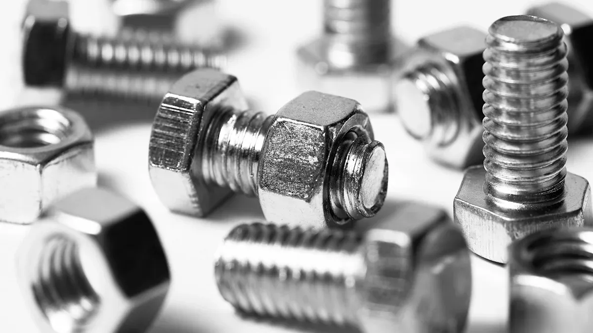
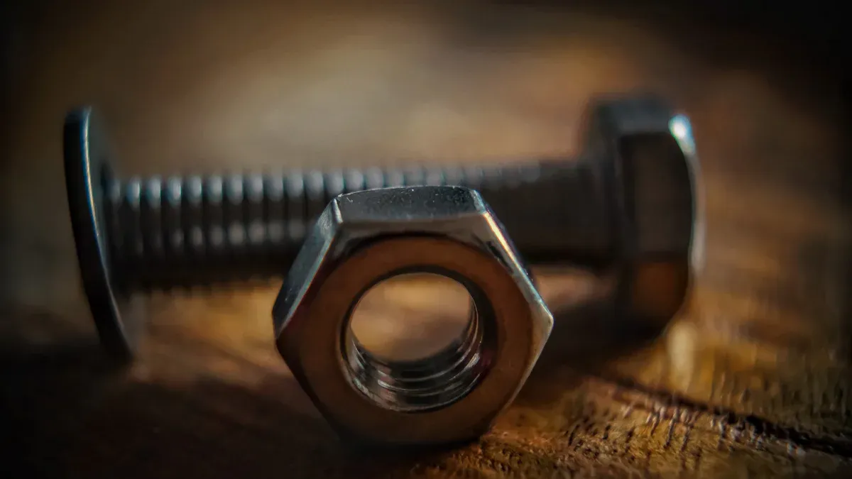
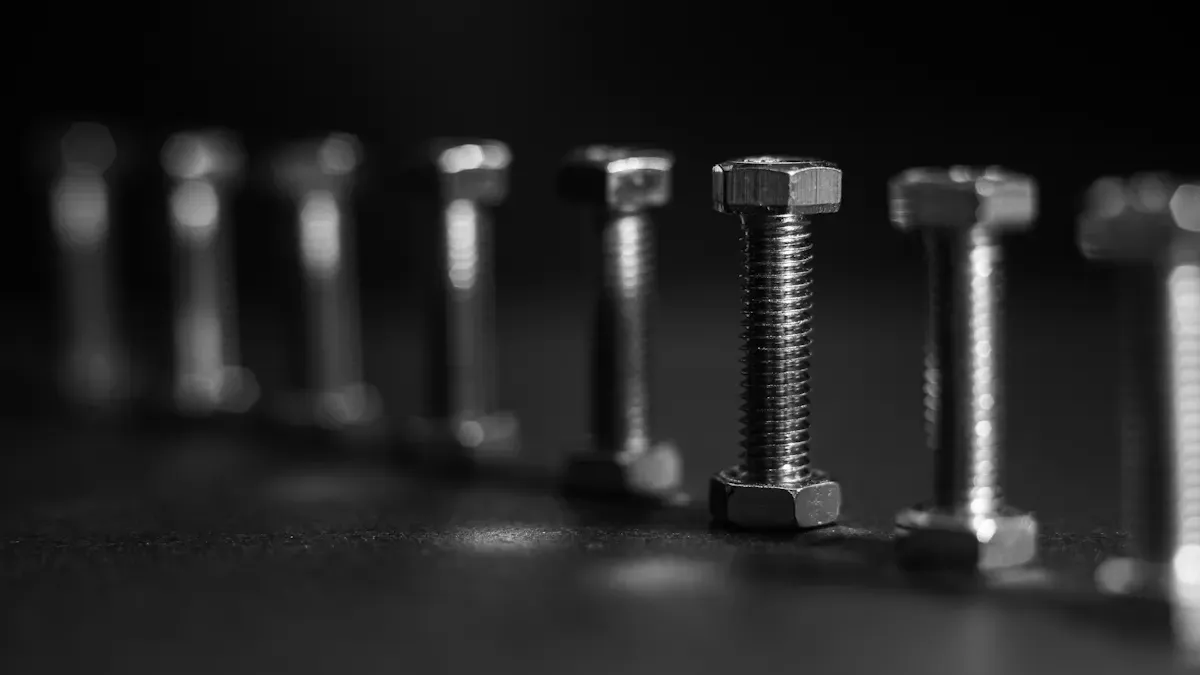
The Israeli sleeve anchor is a through‑fixing expansion fastener comprising a threaded stud, a slotted sleeve, an expansion cone, a washer, and a hex nut. Tightening the nut draws the cone into the sleeve, expanding it radially against the borehole wall and creating friction and localized bearing. The system suits normal‑weight concrete, solid brick, and concrete masonry units (CMU), enabling immediate service readiness without adhesive cure time.
LSI keywords used: mechanical expansion anchor, torque‑controlled anchor, masonry fastener, through‑bolt sleeve anchor, radial expansion, cracked concrete, CMU, ICC‑ES, ETA, EN 1992‑4, ACI 318, zinc‑plated steel, 304 stainless steel, 316 stainless steel, edge distance, embedment depth, proof load testing.
Components and Operating Principle
Component Breakdown
- Threaded stud: transfers axial tension and shear loads into the base material.
- Expansion cone/wedge: converts axial draw into radial expansion.
- Slotted sleeve: expands against the borehole wall; slot geometry and hardness govern contact stress distribution.
- Washer: spreads clamping force beneath the nut.
- Hex nut: interface for torque application, controlling expansion.
How Expansion Creates Holding Power
Applying torque advances the nut while the cone is drawn into the sleeve. The sleeve expands radially, increasing normal stress at the hole interface. Friction plus local bearing provide resistance to tension and shear. Capacity depends on embedment depth, base material compressive strength, hole size and cleanliness, sleeve geometry, edge distance, spacing, and torque accuracy.
Selection Criteria: Variant, Size, and Material
Variants and Head Forms
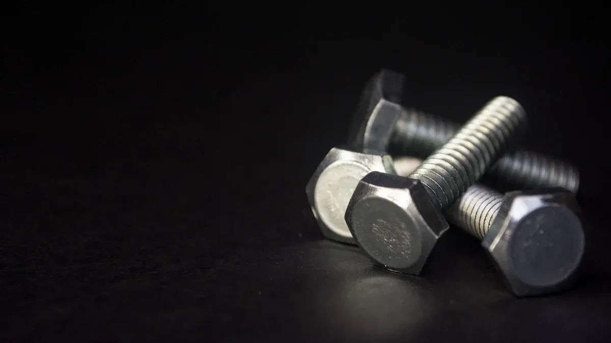
- Through‑bolt with hex nut and washer (most common and globally available).
- Trim or countersunk heads exist regionally; verify fixture compatibility.
Diameter and Length Selection
- Diameter determined by design loads, substrate, and edge/spacing limits; larger diameters increase sleeve contact area.
- Length must account for fixture thickness, washer/nut stack, and minimum embedment (hef), plus a dust allowance.
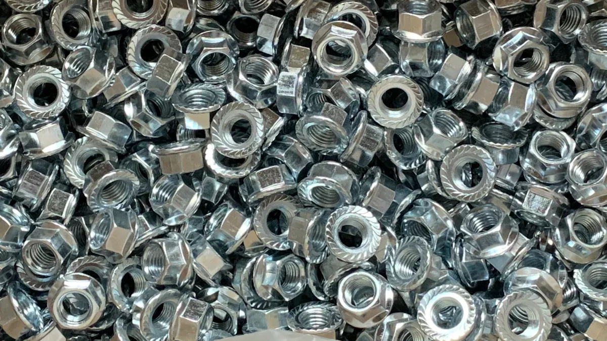
Material and Corrosion Class
| Environment/Exposure | Recommended Material | Rationale | Lifecycle Note |
|---|---|---|---|
| Dry interior | Zinc‑plated carbon steel | Economical; low humidity risk | Lowest upfront cost |
| Humid interior/general exterior | 304 stainless | Broad atmospheric resistance | Lower maintenance |
| Coastal/marine/de‑icing | 316 stainless | Molybdenum‑enhanced pitting resistance | Extended service life |
| Wastewater/chemical splash | 316 stainless | Better resistance to chlorides/sulfides | Fewer replacements |
Evidence: 316 stainless contains molybdenum, improving resistance to chloride‑induced pitting compared with 304, consistent with ISO 9223 atmospheric classification practice and standard corrosion literature.
Tools, Preparation, and Site Controls
- Rotary hammer or hammer drill; carbide‑tipped bit matching anchor nominal diameter.
- Hole cleaning kit: blow bulb or HEPA vacuum and nylon brush sized to the hole.
- Calibrated torque wrench with appropriate socket.
- Depth gauge/stop collar; marker for layout.
- PPE: eye/ear protection, gloves, and respirator per silica dust regulations.
Site controls: verify substrate condition; pre‑mark edge distance and spacing; implement dust control per OSHA 29 CFR 1926.1153 in the U.S. or applicable EU directives.
Step‑by‑Step Installation
- Survey and layout — Validate anchor size vs fixture and embedment; mark hole centers respecting edge distance and spacing.
- Drill the borehole — Use a sharp carbide bit of the nominal diameter; drill perpendicular to depth (embedment plus dust allowance).
- Clean the hole — Perform blow–brush–blow cycles or HEPA extraction until dust is minimal.
- Insert and seat — Place the fixture; insert the sleeve anchor; ensure washer and nut seat flat.
- Apply torque — Tighten the nut to the manufacturer‑specified torque using a calibrated wrench; avoid impact drivers for final set.
- Verify and document — Record applied torque and conduct proof tests as required.
Torque Specification, Verification, and Troubleshooting
Indicative Torque Ranges
- 3/8 in (≈M10): ~20 ± 5 ft·lbf (27 ± 7 N·m)
- 1/2 in (≈M12): ~40 ± 10 ft·lbf (54 ± 14 N·m)
Always follow the product data sheet or evaluation report for exact values.
Verification Practices
- Maintain current calibration certificates for torque tools.
- Audit a sample of installed anchors for torque accuracy.
- Proof load 40–50% of design tension on critical anchors.
Troubleshooting
- Anchor spins: likely oversize/dusty hole or weak substrate; re‑drill, clean, and respect edge distance.
- Fixture lift‑off: under‑torque or insufficient embedment; re‑torque or upsize/extend embedment.
- Substrate cracking: over‑torque or edge proximity; reduce torque, increase edge distance, or change system.

Layout Rules: Embedment, Edge Distance, Spacing
- Embedment: meet or exceed product minimum hef to develop capacity and ensure thread engagement after fixture thickness.
- Edge distance and spacing: preliminary 8–10× diameter; apply product‑specific reductions only if permitted.
- Avoid stand‑off unless evaluated; prying can amplify tension.
Substrate‑Specific Guidance: Concrete, Brick, Hollow CMU
Normal‑Weight Concrete
Offers consistent performance. For cracked concrete, confirm cracked‑concrete evaluation (e.g., ICC‑ES AC193/ESR) and apply associated factors and seismic provisions where required.
Solid Brick or Natural Stone
Drill into solid units, not mortar joints. Use conservative torque to reduce cracking risk in brittle units. Verify compressive strength variability.
Hollow CMU
Target the web, control depth, and expect lower, more variable capacities. For higher loads or reduced edge distances, consider adhesive anchors with screens.
Safety, Dust Control, and Environment
- Implement silica dust controls (HEPA extraction or wet methods if allowed).
- Maintain PPE and exclusion zones under overhead work.
- Observe temperature classes in the evaluation; re‑verify torque after thermal cycling for critical fixings.
Quality Assurance and Field Testing
Documentation
- Record torque wrench calibration status, anchor batch/heat numbers, material grade, size, and applied torque.
Testing and Inspection
- Proof testing at 40–50% of design tension to verify installation without damage.
- Pull testing as specified; avoid exceeding elastic limits.
Common Pitfalls and Corrective Actions
- Dirty or oversize holes: re‑drill correct size; blow–brush–blow until clean.
- Misaligned drilling: re‑drill perpendicular; avoid elongated holes.
- Insufficient embedment: select longer anchors to meet hef and preserve thread engagement.
- Edge violations: relocate, reduce diameter with increased quantity, or switch to systems evaluated for close edges.
Comparative Notes vs Alternative Anchors
- Sleeve vs wedge: sleeve anchors tolerate hole variability and masonry; wedge anchors are higher‑capacity in sound, uncracked concrete.
- Sleeve vs concrete screw: screws are removable and quick but hole‑sensitive; sleeve anchors provide predictable torque‑controlled expansion.
- Sleeve vs adhesive: adhesives can reach high capacities with controlled installation/curing; sleeve anchors allow immediate loading and simpler QA/QC.
Procurement and Documentation Checklist
- Anchor designation, diameter × length, head form.
- Material/coating: zinc‑plated, 304, or 316 stainless.
- Evaluation reference (ICC‑ES ESR/ETA), governing code (ACI 318, EN 1992‑4).
- Required embedment, edge distance/spacing, installation torque.
- Fixture thickness and required thread engagement.
- Exposure category and temperature range.
- QA plan: torque logs, proof‑test sampling, acceptance criteria.
FAQs
1) Can Israeli sleeve anchors be used in cracked concrete?
Yes, if the product has cracked‑concrete evaluation (e.g., ICC‑ES ESR to AC193 or an ETA covering cracked concrete). Apply reductions and seismic provisions accordingly.
2) What torque should be applied?
Follow the specific product data sheet. Indicatively ~20–25 ft·lbf for 3/8 in and ~35–50 ft·lbf for 1/2 in, applied with a calibrated wrench.
3) How should installation be adapted for hollow CMU?
Drill/set in the web, control depth, use conservative torque, and expect lower, more variable capacities. Consider adhesive anchors with screens for higher loads.
4) What causes installation failures most often?
Oversize/dusty holes, improper torque, inadequate embedment, and edge/spacing violations. Correct by re‑drilling to size, thorough cleaning, calibrated torque, and proper layout.
5) How do sleeve anchors compare for productivity?
In mixed masonry/concrete, sleeve anchors reduce rework and allow immediate loading. Wedge anchors can be faster/higher capacity in quality concrete; concrete screws are removable but hole‑sensitive.
References and Outbound Links
Use the selected product’s current evaluation report and data sheet for design. Authoritative resources:
- ICC‑ES Evaluation Reports: https://www.icc-es.org/evaluation-reports/
- American Concrete Institute (ACI 318; ACI 355): https://www.concrete.org/
- EN 1992‑4 overview (JRC): https://eurocodes.jrc.ec.europa.eu/showpage.php?id=136
- The Masonry Society (TMS 402/602): https://masonrysociety.org/
- ASTM (B633 zinc plating; F593/F594 stainless): https://www.astm.org/
Attribution: Content compiled from professional practice and public standards/evaluation frameworks (ICC‑ES, ACI, EN 1992‑4, TMS). Typography settings are explicitly displayed above as requested.