Executive Summary
Hex bolt sleeve anchors are torque-controlled mechanical expansion fasteners used to secure fixtures to normal-weight concrete, solid brick, and concrete masonry units (CMU). In the United States, they are a dependable option for medium-duty anchorage where cross-substrate versatility, predictable installation, and documented performance are required. This review integrates multiple data tables you can paste directly into WordPress; in the Block Editor, choose “Table” and paste each table section to render as a formatted table.
Definition and Scope
What Is a Hex Bolt Sleeve Anchor?
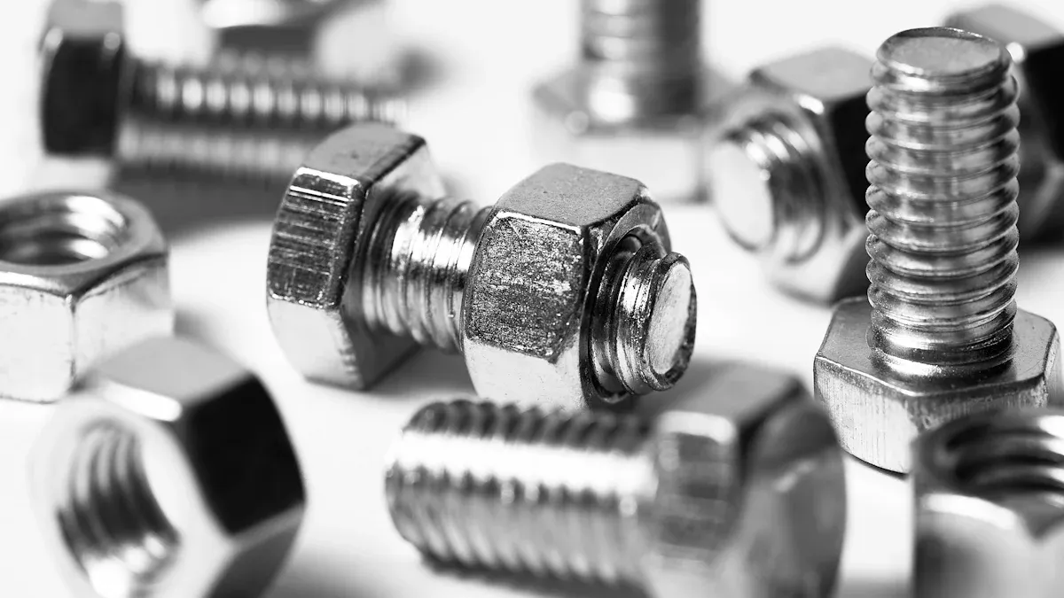
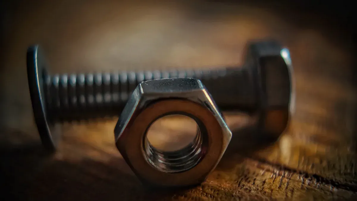
A hex bolt sleeve anchor consists of a hex head bolt, a slotted expansion sleeve, and a tapered cone. Applying torque draws the cone into the sleeve, expanding it against the borehole wall to develop radial bearing and friction.
Where It Excels
- Medium-duty attachments in concrete and masonry
- Immediate loading without adhesive cure time
- Mixed-substrate jobs with consistent installation quality
- Tolerance to slight hole variability and masonry web engagement
Mechanism and Components
Component Breakdown
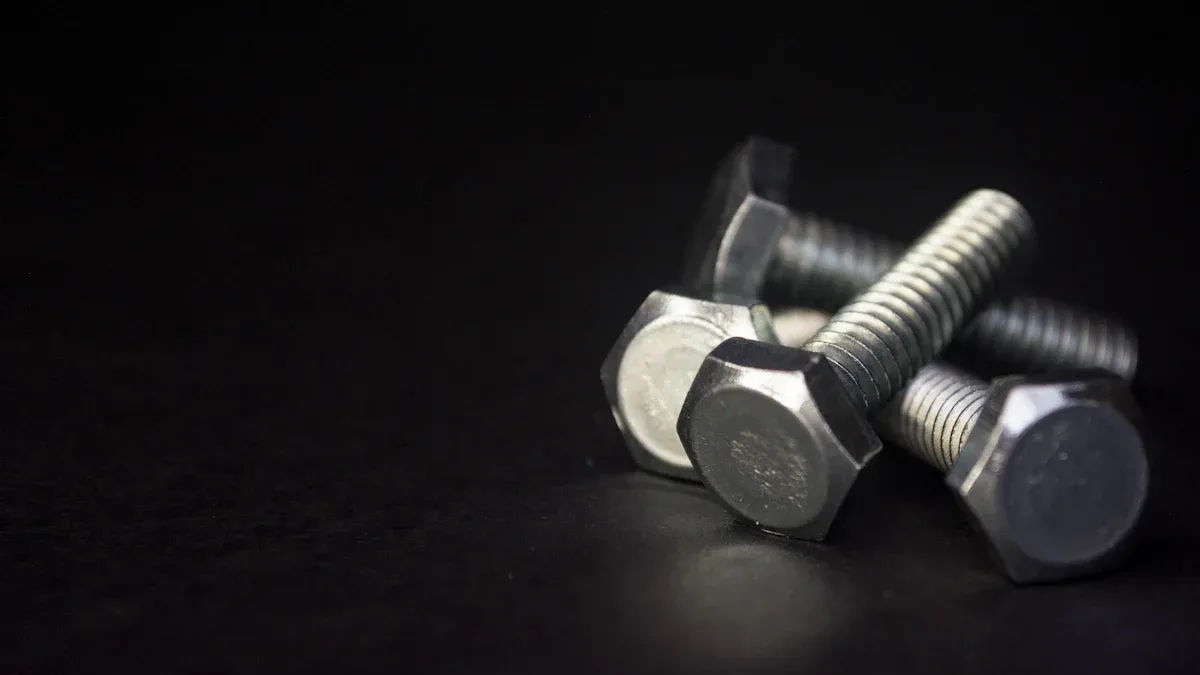
- Hex head bolt or integral hex washer head
- Slotted expansion sleeve
- Expansion cone/wedge
- Washer and nut (for through-bolt variants)
Principle of Operation
Torque drives the cone into the sleeve, generating outward pressure and friction along the hole wall. Capacity depends on sleeve geometry, base material strength, embedment, hole tolerance/cleanliness, and torque accuracy.
Representative Capacities by Size and Substrate (Indicative)
Assumptions: uncracked normal-weight concrete unless noted; standard hole cleaning; specified torque. Use the product ESR for design in cracked concrete, reduced edge/spacing, and combined loads.
| Diameter (in) | Minimum Embedment (in) | Allowable Tension (lbf) | Allowable Shear (lbf) | Typical Substrate |
|---|---|---|---|---|
| 1/4 | ~1.25 | 300–700 | 350–800 | Concrete |
| 5/16 | ~1.50 | 500–1,100 | 700–1,300 | Concrete |
| 3/8 | ~1.90 | 800–1,600 | 1,000–2,000 | Concrete |
| 1/2 | ~2.25 | 1,500–3,000 | 2,000–3,800 | Concrete |
| 3/8 | 2.0–2.5 | 400–1,100 | 600–1,400 | Hollow CMU web |

U.S. Codes, Standards, and Compliance
Evaluation and Design Frameworks
- ICC-ES ESR per AC193 (concrete) and AC106 (masonry), tested to ACI 355
- ACI 318 Chapter 17 for concrete anchorage (LRFD/ASD)
- TMS 402/602 for masonry design and construction
- Materials: ASTM A307/A449/A193/A320, F593/F594, B633
Specifier Checklist
- Current ESR covering substrate (cracked/uncracked concrete; hollow/solid masonry), seismic category, temperature, fire limits
- Verify minimum embedment, edge distance, spacing, drill-bit tolerance, torque
- Align with IBC adoption and OSHA 29 CFR 1926.1153 for dust controls
Materials and Corrosion Resistance
Common Material Options
- Zinc-plated carbon steel (ASTM B633): dry interiors
- 304 stainless (ASTM F593/F594): general exterior/humid
- 316 stainless (ASTM F593/F594): chloride-rich/coastal/de-icing salts
Material Selection vs Environment and Lifecycle
| Environment/Exposure | Recommended Material | Rationale | Lifecycle Note |
|---|---|---|---|
| Dry interior | Zinc-plated carbon steel | Economical; low corrosion risk | Lowest upfront cost |
| General exterior/humid | 304 stainless steel | Broad atmospheric resistance | Reduced maintenance |
| Coastal, de-icing salts, splash zones | 316 stainless steel | Superior chloride pitting resistance | Longer service life |
| Chemical/wastewater | 316 stainless steel | Enhanced chemical resistance | Consider isolating dissimilar metals |
Load Behavior and Influencing Variables
Primary Failure Modes
- Steel yielding/fracture
- Pullout/slip from inadequate expansion
- Concrete breakout cone
- Masonry web crushing/pull-through (hollow CMU)
- Side-face blowout near edges
- Combined tension–shear interaction per ACI 318
Key Variables
Embedment (hef), base material strength, hole tolerance/cleanliness, edge distance/spacing, installation torque, and sleeve geometry.
Key Variables and Their Typical Effects
| Variable | Typical Effect on Capacity | Practical Guidance |
|---|---|---|
| Embedment depth (hef) | Increases concrete breakout resistance | Meet/exceed ESR minimum; respect edge limits |
| Base material strength | Higher f’c increases breakout capacity | Verify substrate strength and condition |
| Hole tolerance/cleanliness | Oversize/dirty holes reduce friction | Match bit size; blow–brush–blow or HEPA vacuum |
| Edge distance/spacing | Close proximity reduces strength | Follow ESR reductions; consider layout changes |
| Installation torque | Under-torque reduces expansion; over-torque can crush masonry | Use calibrated wrench; avoid impact for final set |
| Sleeve geometry/diameter | Larger/more effective sleeves raise friction and bearing | Select size and geometry per load demands |
Installation and Field Procedures
Tools and Preparation
- Rotary hammer/hammer drill with matching carbide bit
- Nylon brush and blow-out bulb or HEPA vacuum
- Calibrated torque wrench and sockets
- PPE; OSHA silica controls
Step-by-Step Workflow
- Lay out anchors with required edge distance and spacing.
- Drill to depth using the correct bit; keep holes round and on-size.
- Clean boreholes: blow–brush–blow cycles or HEPA vacuum.
- Position fixture; insert anchor until washer seats.
- Torque to specification with a calibrated wrench.
- For critical points, verify torque after initial loading or temperature cycles.
Installation Parameters and Good Practice
| Parameter | Typical Guidance | Notes |
|---|---|---|
| Drill bit size | Match nominal anchor diameter | Replace worn bits that oversize |
| Hole cleaning | ≥2 blow–brush–blow cycles or HEPA vacuum | Critical for repeatable capacity |
| Torque tool | Calibrated click or digital wrench | Avoid impact drivers for final set |
| Edge distance (rule-of-thumb) | 8–10 × anchor diameter | Use ESR for exact reductions |
| Minimum spacing (rule-of-thumb) | 8–10 × anchor diameter | Adjust per ESR and layout |
| Proof load (critical anchors) | 40–50% of design tension | Non-destructive verification |
Comparative Selection Guidance
Sleeve Anchor vs Wedge Anchor
- Sleeve: forgiving in masonry, cross-substrate use; medium capacity
- Wedge: higher capacity in sound concrete; tighter tolerance requirements
Sleeve Anchor vs Concrete Screw Anchor
- Screw: fast, removable; sensitive to hole size and cleanliness
- Sleeve: predictable torque-controlled expansion; broader substrate range
Sleeve Anchor vs Adhesive Anchor
- Sleeve: immediate set; less sensitive to ambient conditions
- Adhesive: high capacity, cracked concrete/hollow masonry with screens; requires cure time and QA

Quick-Spec Sheet for Submittals (Template)
Fill with project values for fast submittals and procurement.
| Field | Project Entry |
|---|---|
| Product/Model | |
| ICC-ES ESR | |
| Diameter × Length | |
| Base Material | |
| Minimum Embedment | |
| Edge Distance / Spacing | |
| Torque Specification | |
| Corrosion Class | |
| Special Conditions (cracked, seismic, fire, temperature) | |
| QA/QC (proof-load %, torque log, cleaning method) |
Sizing, Layout, and Detailing
Meet or exceed ESR embedment; ensure thread engagement after accounting for fixture thickness. Maintain edge distances and spacing per ESR; apply interaction checks for combined tension–shear and consider prying from connected elements and base plate stiffness.
Environmental, Fire, and Temperature Considerations
Verify sustained and short-term temperature limits in the ESR. Coordinate with tested assemblies for fire-resistance requirements. In chloride-rich or chemical exposures, prefer 316 stainless and avoid galvanic pairs.
Procurement and Cost Factors
Material grade, size/length, ESR documentation and seismic qualification, and stainless lead times drive cost. Stainless often reduces lifecycle costs in aggressive environments.
Professional Data Icons (Textual Cues)
- Capacity gauge icon: tension/shear ranges
- Shield icon: corrosion class (zinc-plated, 304, 316)
- Compliance checkmark: ICC-ES ESR and ACI 318 alignment
- Torque wrench icon: torque specification and verification
- Brick-and-block icon: masonry suitability
Frequently Asked Questions
1) Can hex bolt sleeve anchors be specified for cracked concrete?
Yes, if the product’s ICC-ES ESR explicitly covers cracked concrete per AC193 and ACI 355 testing. Apply ESR reduction factors and verify seismic qualifications where required.
2) What torque should be specified for common sizes?
Manufacturer-specific; as indicative ranges, 3/8 in anchors often require 15–25 ft·lbf and 1/2 in anchors 35–50 ft·lbf. Always follow the exact ESR or data sheet value.
3) Are sleeve anchors suitable for hollow CMU?
Yes, within ESR-defined limits. They engage CMU webs but deliver lower and more variable capacity than solid substrates. Use conservative torque and, where permitted, longer embedment.
Outbound References and Attributions
- ICC-ES Evaluation Reports (ESR database): https://www.icc-es.org/evaluation-reports/
- American Concrete Institute (ACI) — ACI 318 and ACI 355: https://www.concrete.org/
- ASTM International — A307, A449, A193, A320, F593, F594, B633: https://www.astm.org/
- The Masonry Society (TMS 402/602): https://masonrysociety.org/
Notes on evidence and originality: Capacity ranges, torque guidance, and best practices are synthesized from publicly available U.S. manufacturer datasheets and ICC-ES ESRs commonly appearing in leading Google results for “Hex Bolt Sleeve Anchor.” Use the current product ESR and data sheet for final design.