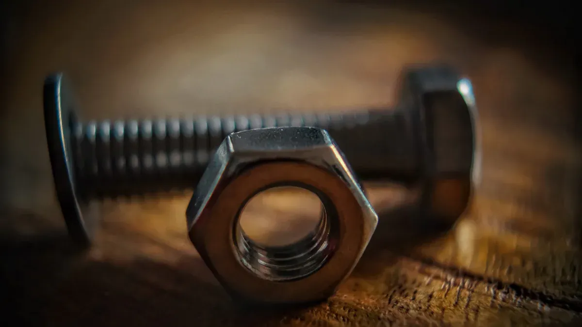
Выбор правильной гайки анкерные болты is critical for a safe light pole installation. The industry standard specifies hot-dip galvanized, L-type or J-type steel bolts meeting ASTM F1554 Grade 55. Proper anchor bolt sizes depend on the light pole’s height, weight, and environmental loads. A производитель крепежных изделий на заказ often produces these нестандартные крепежные элементы to meet precise engineering requirements.
There is no universal solution for these components. A project’s structural plans dictate the exact specifications for all специальные анкерные болты. This ensures the foundation’s integrity and long-term stability.
Fundamentals of Anchor Bolts for Light Poles

Anchor bolts form the critical link between a concrete foundation and the light pole itself. Installers insert these fasteners into wet concrete, using a template to ensure a perfect fit for the pole’s base plate. Their primary function is to secure the pole to the foundation and maintain its stability. A failure in these анкерные болты compromises the entire structure’s integrity. Understanding the different types of anchor bolts, materials, and coatings is essential for a successful project.
Common Anchor Bolt Types
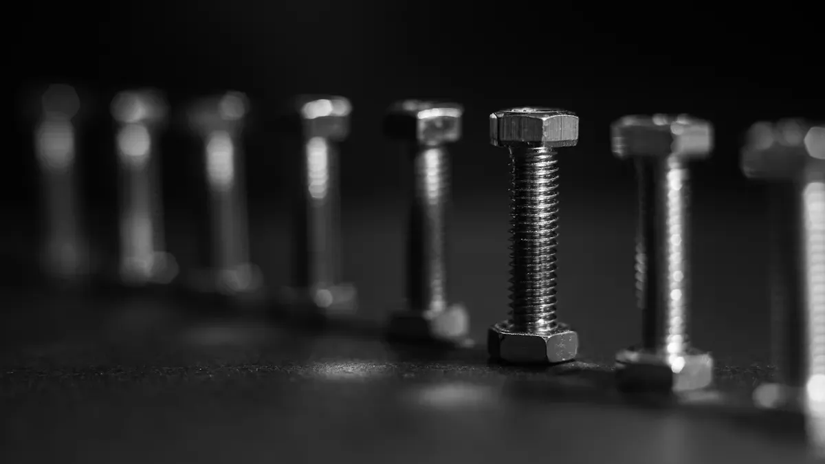
Engineers select from several common designs based on the required holding strength and foundation engineering.
L-Type (Bent-Anchor) Bolts
L-type bolts feature a 90-degree bend at the non-threaded end. This “L” shape provides excellent resistance against pull-out forces once embedded in concrete, making it a very common choice for light pole applications.
J-Type Bolts
Similar to the L-type, the J-type bolt has a curved, hook-shaped end. This hook also provides strong mechanical anchoring within the concrete, resisting tension and shear forces effectively.
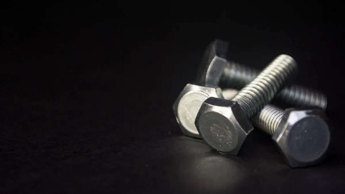
Headed Anchor Bolts with Plate
This configuration uses a straight, headed bolt, often with a steel plate and nut at the embedded end. The plate significantly increases the bearing surface area, offering maximum resistance to pull-out for heavy-duty or high-load scenarios.
Critical Material Specifications: ASTM F1554
Стандарт DIN 933: объяснение ASTM F1554 specification governs the manufacturing of anchor bolts, ensuring they meet specific chemical and mechanical properties. It is divided into three strength grades.
| Класс прочности | Minimum Yield Strength (ksi) | Tensile Strength Range (ksi) |
|---|---|---|
| 36 | 36 | 58 – 80 |
| 55 | 55 | 75 – 95 |
| 105 | 105 | 125 – 150 |
ASTM F1554 Grade 36
Grade 36 is a low-carbon steel suitable for general-purpose anchoring with lower load demands. It offers good ductility but is less common for structural light pole installations.
ASTM F1554 Grade 55
Отраслевой стандарт: Grade 55 is the most specified material for light pole and traffic signal supports. Made from a modified mild steel, it provides an excellent balance of strength and cost-effectiveness. Its use in these applications predates the 1994 F1554 standard, demonstrating its long-standing reliability.
ASTM F1554 Grade 105
Grade 105 is a high-strength, heat-treated alloy steel. Engineers reserve this grade for applications with extreme tensile loads, such as very tall poles or structures in high-wind zones.
The Role of Protective Coatings
A protective coating is vital for preventing corrosion and ensuring the long-term durability of anchor bolts.
Hot-Dip Galvanization (ASTM A153)
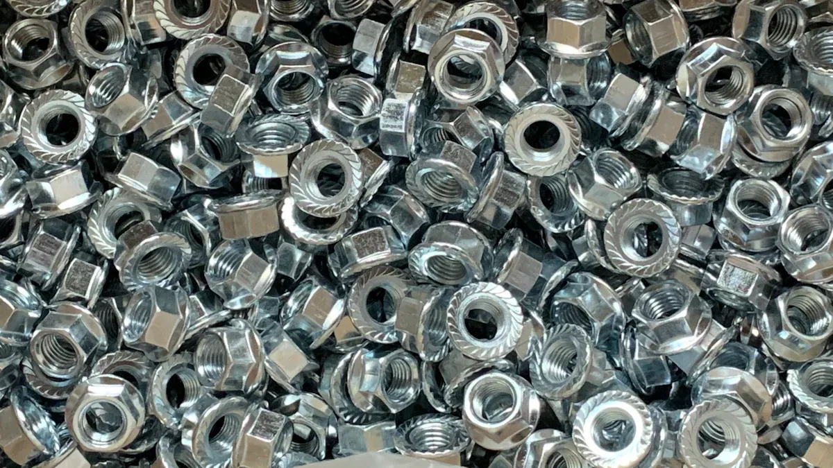
Hot-dip galvanization is the most common and effective corrosion protection method. The process creates a durable, metallurgically bonded zinc coating that offers reliable, maintenance-free performance in most outdoor environments.
Stainless Steel Bolts
Project specifications call for stainless steel in highly corrosive areas.
- Environments with salt water or salt-laden air require stainless steel.
- It prevents galvanic corrosion that can occur when dissimilar metals are in contact.
Weathering Steel (A588)
Weathering steel, often specified by its ASTM A588 designation, develops a stable, rust-like patina over time. This outer layer protects the steel from further corrosion and is chosen when a specific aesthetic is desired to match a weathering steel light pole.
How to Select the Correct Anchor Bolts
Выбор правильной гайки анкерные болты is a process driven by engineering principles, not guesswork. Installers must analyze several interconnected factors to ensure the chosen fasteners can support the structure safely for its entire service life. The final selection always comes from the project’s official engineering plans, which synthesize these critical variables into a precise specification.
Key Factors in Bolt Selection
Engineers consider four primary elements when specifying the correct anchor bolt sizes and grades for a project. Each factor contributes to the overall load calculations that the fasteners must withstand.
Pole Specifications
The physical characteristics of the light pole are the starting point. Its height, weight, and material directly impact the forces transferred to the foundation. Taller, heavier poles naturally exert greater loads, requiring stronger, and often larger diameter, anchor bolts to secure them.
Environmental Loads
Environmental forces, especially wind, are a primary concern. Engineers calculate the pole’s resistance to wind using a value called Effective Projected Area (EPA). This calculation accounts for the surface area of the pole plus all attachments like luminaires, brackets, and banners.
Calculating Total EPA Manufacturers use the total EPA and the project site’s maximum wind speed to rate a pole. The process involves these steps:
- Identify all fixtures, brackets, and accessories for the pole.
- Calculate the total EPA using the formula:
(EPA of fixtures × quantity) + (EPA of brackets × quantity) + (EPA of accessories × quantity).- Reference a wind map to determine the maximum wind velocity for the installation area.
- Provide the total EPA and wind velocity to the manufacturer.
- The manufacturer confirms if the selected light pole is suitable or recommends adjustments.
Foundation Design
The concrete foundation is engineered in tandem with the light pole and its fasteners. The foundation’s depth and reinforcement design dictate the required embedment depth of the bolts. Deeper embedment provides greater resistance to pull-out forces, ensuring the entire assembly acts as a single, stable unit.
Base Plate Configuration
The pole’s base plate must align perfectly with the anchor bolts. The thickness of the base plate, along with the size of the bolt holes, determines the required bolt diameter. The configuration also influences the necessary bolt projection—the length of the threaded end extending above the concrete—to accommodate leveling nuts, washers, and the final anchor nut.
Interpreting Engineering Plans
Structural drawings are the definitive guide for any installation. These documents contain all the necessary details for a safe and compliant project. Knowing how to locate and interpret this information is a critical skill.
Locating the Bolt Schedule
Installers can typically find anchor bolt specifications in a “General Notes” section or a dedicated “Bolt Schedule” on the structural drawings. This schedule provides a clear, itemized list of all fasteners required for the project, including their grade, diameter, length, and protective coating.
Understanding Specification Callouts
Engineering plans use standardized callouts to define bolt materials. While ASTM F1554 is the current standard for anchor bolts, older specifications may still appear on some plans. Understanding these designations is essential for procuring the correct materials.
| Спецификация | Классы прочности | Key Characteristics for Light Poles |
|---|---|---|
| A307 | A, C | Grade A is for general use. Grade C was superseded by F1554 Grade 36 but is still sometimes specified in the lighting industry. |
| F1554 | 36, 55, 105 | This is the dedicated specification for bolts used in a concrete foundation. Grade 55 is the industry standard for its high yield strength. |
| A449 | Н/Д | This is a heat-treated, higher-strength steel. It is often used for its strength and adaptability in demanding lighting applications. |
Verifying Bolt Circle and Projection
Accuracy is paramount when setting bolts. Two key measurements are the bolt circle and projection.
- Bolt Circle: This is the diameter of a circle running through the center of each bolt in the pattern. For a typical four-bolt square pattern, installers determine this by measuring the distance from the center of one bolt to the center of the diagonally opposite bolt. A precise bolt circle ensures the pole base will fit over the bolts without issue.
- Projection: This is the length of the bolt extending above the concrete surface. The specified projection must be achieved to allow room for the leveling nut, base plate, washer, and anchor nut, ensuring proper tightening is possible.
Best Practices for Light Pole Installation

A successful light pole installation depends on meticulous execution at every stage, from initial site preparation to final tightening. Following established best practices ensures the structure is safe, stable, and compliant with engineering designs. Proper technique prevents costly rework and guarantees long-term performance.
Pre-Pour Preparation
Careful preparation before the concrete arrives is the most critical phase for ensuring accuracy. Errors made at this stage are difficult, if not impossible, to correct later.
Assembling the Bolt Cage
Installers assemble the анкерные болты into a rigid “cage” using a rebar framework. This cage maintains the bolts’ vertical alignment and embedment depth within the concrete form. For enhanced structural integrity, engineers may specify additional components:
- Angle bracing: Diagonal supports reinforce the cage against lateral forces during the concrete pour.
- Stiffener rings: These are welded to the top template to preserve the bolt circle’s integrity during handling.
- Concrete reinforcement rings: Circular steel rebar tied to the cage increases the foundation’s overall strength.
- Lifting lugs: Attachments on the cage simplify lifting and placement with machinery.
Using a Rigid Steel Template
A rigid steel template is essential. It holds the top of the bolts in the precise pattern required by the pole’s base plate. Cardboard or thin plywood templates can warp or fail, leading to bolt misalignment. A steel template, often with V-notches for alignment, guarantees the bolt circle diameter and spacing remain correct throughout the installation process.
Protecting Bolt Threads
The exposed threads of the anchor bolts must be protected from concrete spatter and physical damage. While tape is common, it can be easily torn. A more robust method involves slipping short pieces of PEX tubing over the threads. Installers can embed the tubing an inch or two into the wet concrete, leaving enough length to cover the threads completely. This chemical-resistant tubing provides superior protection and is simply cut away after the concrete cures.
The Concrete Pour and Curing
The concrete pour locks the bolt assembly into its final position. Precision and patience during this phase are paramount for the stability of the entire concrete foundation.
Securing the Template During Pour
The entire bolt cage and template assembly must be securely suspended in the excavation. Installers typically use heavy-duty wire to hang the assembly from wood or steel beams laid across the hole.
Positioning is Key 🔑 The cage must be perfectly centered and level. The top of the rebar cage must sit below the final concrete surface to ensure complete coverage. The template itself must remain above the concrete to prevent it from becoming embedded.
Verifying Projection Height
Immediately after the concrete is poured and leveled, installers must re-verify the bolt projection height. They measure from the surface of the wet concrete to the top of each bolt. If the assembly has shifted, they must make immediate adjustments before the concrete begins to set.
Understanding Concrete Cure Times
Concrete does not achieve its full design strength overnight. The project engineer will specify the required compressive strength (measured in PSI) that the concrete must reach before it can bear the load of the light pole. This curing process typically takes a minimum of 7 days, but a full 28-day cure is often required for maximum strength. Attempting to install a pole prematurely can lead to foundation failure.
Post-Cure and Pole Setting
Once the concrete has fully cured and been tested, the final installation of the light pole can begin. This final stage requires a focus on leveling and proper tightening procedures.
Leveling Nut Procedure
Installers thread one leveling nut and washer onto each bolt, adjusting them to the same elevation. A laser or transit level ensures all leveling nuts are in a perfectly flat plane. The pole base will rest on these nuts, which allows for fine-tuning to make the pole perfectly plumb (vertically straight).
Pole Placement and Grouting
A crane carefully lifts and lowers the pole, guiding its base plate over the bolts and onto the leveling nuts. After the pole is set and plumbed, installers fill the space between the bottom of the base plate and the top of the concrete foundation with a non-shrink grout. This grout provides uniform support and transfers the load evenly across the foundation.
Final Tightening and Torque Specs
After the grout has cured, installers place the top washers and nuts. According to AISC guidelines, the standard procedure is to tighten the nuts to a “snug-tight” condition. An ironworker achieves this by applying full effort with a standard spud wrench.
Important Note on Torque: Specific torque values are generally not required unless explicitly detailed by the project engineer for a high-load or moment-resisting design. Manufacturers do not provide application-specific torque values. Any requirement for pretensioning beyond snug-tight must be defined in the structural plans.
Advanced Topics and Special Scenarios
Not every installation involves a brand-new foundation. Installers often face challenges with existing concrete, requiring specialized retrofitting and repair techniques. These scenarios demand careful assessment and the correct application of advanced solutions to ensure a safe and durable outcome.
Retrofitting and Repair Solutions
When existing fasteners are missing, damaged, or incorrectly placed, installers must employ specific methods to prepare the foundation for a new pole.
Using Epoxy Anchors
Installers use adhesive epoxy anchors when cast-in-place bolts are not feasible. This system involves drilling a hole and securing a threaded rod with a high-strength, two-part epoxy. Epoxy is a reliable solution under specific conditions.
- It is suitable for passive dowels or anchors that do not face sustained tension.
- It performs well for concrete anchors primarily loaded in shear.
- Manufacturers explicitly list light pole installations as an appropriate application.
Core Drilling for New Anchors
For significant misalignments or when a completely new pattern is required, core drilling is a viable option. This process uses a specialized drill to cut a large, precise hole through the existing concrete foundation. Installers can then place a new fastener assembly and secure it with non-shrink grout or epoxy, creating a robust new anchor point.
Repairing Damaged Threads
Field conditions can lead to damaged threads on cast-in-place bolts. For minor damage, an installer can use a thread-chasing die to clean and reform the threads. If the damage is severe or the bolt projection is too short, a threaded bolt extender or coupling nut may be necessary to achieve proper nut engagement.
Working with Existing Foundations
Reusing an existing foundation can save significant time and money, but it requires a thorough verification process. An installer must never assume an old foundation is suitable without a complete inspection.
Verifying Existing Bolt Patterns
Before ordering a new light pole, installers must confirm the existing foundation’s bolt pattern and condition with precise measurements.
- Inspect the Bolts: First, they clean any rust or debris from the existing bolts and check for signs of corrosion or damage.
- Determine Pattern Size: They measure the bolt pattern from the center of one bolt to the center of another. For a square pattern, they measure both the diagonal distance (bolt circle) and the adjacent distance (bolt square) to account for any bending.
- Check Bolt Diameter: They determine the diameter of the existing bolts to ensure the new pole’s base plate holes will fit.
- Assess Bolt Projection: Finally, they measure the bolt projection above the concrete to confirm there is enough length for leveling nuts, washers, and the final anchor nut.
Assessing Foundation Integrity
A visual inspection of the concrete itself is critical. Installers look for signs of degradation, such as significant cracking, chipping, or spalling (where concrete flakes away).
Safety First ⚠️ If the foundation shows any signs of structural compromise, a qualified structural engineer must assess its integrity before any new pole is installed.
Adapting to Mismatched Patterns
When a new pole’s base plate does not match the existing bolt pattern, a manufactured adapter plate is often the best solution. These hot-dip galvanized steel adapters bolt onto the existing foundation’s studs. They provide a new set of threaded studs in the correct pattern, allowing for adjustments in bolt circle size, rotation, or centering. This method provides a permanent, engineered fix without the need for costly foundation removal.
Common Failures and How to Avoid Them
An excellent light pole installation can last for decades, but common mistakes during and after the pour can lead to premature failure. Understanding these potential pitfalls is the first step toward preventing them. By focusing on precision during installation and proper maintenance afterward, installers can ensure a safe and durable structure.
Ошибки монтажа
Most catastrophic failures originate from errors made before or during the concrete pour. These mistakes are often irreversible and compromise the foundation’s structural integrity from day one.
Неправильная глубина заделки
The embedment depth of a болт is a critical engineering specification. Under-embedding the bolts significantly reduces their load capacity. This insufficient depth heightens the risk of concrete breakout or pull-out failures under load. It can also lead to cracking around the anchor point, which further weakens the foundation and accelerates degradation.
Требуемый диаметр твердосплавного сверла Always double-check the required embedment depth on the engineering plans. Measure from the top of the finished concrete surface to the bottom of the L- or J-hook to confirm compliance before and after the pour.
Bolt Misalignment
A precise bolt pattern is non-negotiable. Misaligned bolts create uneven stress distribution across the base plate, which can overload individual fasteners and lead to structural failure. Installers often encounter bolts misplaced by as little as half an inch, which can complicate the erection schedule and compromise safety.
- Несоосность препятствует равномерному распределению нагрузок, приводя к перегрузке..
- Это может вызвать обрушение всей конструкции, создавая значительные риски.
- Ослабленные или поврежденные из-за несоосности болты могут стать причиной аварий во время технического обслуживания.
Недостаточный защитный слой бетона
Защитный слой бетона — это толщина бетона между стальной арматурой (каркасом из анкерных болтов) и внешней поверхностью фундамента. Этот слой защищает сталь от влаги и коррозионных элементов. Недостаточный слой обнажает арматуру и заделанную часть болтов, что приводит к коррозии и со временем к потере конструкционной прочности.
Проблемы после монтажа
Даже при идеальном монтаже проблемы могут возникнуть в течение срока службы опоры. Эти проблемы часто связаны с техническим обслуживанием, воздействием окружающей среды и силами, действующими на опору.
Неправильная затяжка
Неправильная затяжка, будь то слишком слабая или слишком сильная, создает значительные риски. Чрезмерный момент затяжки может вызвать структурные повреждения как болта, так и опорной плиты, включая усталостные трещины и снижение усталостной долговечности. Это делает соединение склонным к внезапному разрушению под рабочими нагрузками. И наоборот, недостаточно затянутые гайки со временем могут ослабнуть.
Коррозия и деградация материала
Коррозия — главный враг стальных крепежных элементов. Скорость коррозии в значительной степени зависит от условий монтажа.
- Воздействие влаги, солей и загрязнителей воздуха ускоряет ржавление.
- В прибрежных районах соленый воздух может вызывать коррозию стали в десять раз быстрее, чем в сухом континентальном климате.
- Механические повреждения при монтаже могут содрать защитные покрытия, создавая прямой путь для начала коррозии.
Ослабление из-за вибрации
Опоры подвержены постоянным низкоуровневым вибрациям от ветра и движения транспорта. В течение многих лет эти гармонические вибрации могут вызывать медленное откручивание гаек, особенно если они не были затянуты до состояния “плотной затяжки”. Это ослабление снижает силу сжатия опорной плиты, позволяя опоре смещаться, что, в свою очередь, ускоряет износ всех компонентов и увеличивает риск отказа. Регулярные проверки являются ключом к выявлению и устранению ослабленного крепежа.
Успешный монтаж осветительной опоры зависит от точности и соблюдения инженерных стандартов. Монтажники обеспечивают безопасность и долговечность, следуя нескольким ключевым принципам.
- Они должны сверять все спецификации с официальными инженерными чертежами проекта.
- Они выбирают болты ASTM F1554 класса 55 с горячим цинкованием для оптимальной прочности и долговечности.
- Жесткий стальной шаблон гарантирует точное выравнивание болтов, глубину заделки и выступающую длину.
- Соблюдение правильных процедур отверждения бетона и затяжки болтов является обязательным.
Окончательное решение 🛡️.
Частые вопросы
Какой анкерный болт лучше всего подходит для осветительной опоры?
Отраслевым стандартом является стальной болт L-образного или J-образного типа с горячим цинкованием. Он должен соответствовать спецификациям ASTM F1554 класса 55. В чертежах инженера проекта указаны точный размер и длина, необходимые для конкретной опоры и места установки.
Могут ли монтажники повторно использовать старые анкерные болты?
Монтажникам не следует повторно использовать старые болты без тщательной проверки. Квалифицированный инженер должен оценить болты на наличие коррозии, повреждений и правильности заделки. Инженер также проверяет целостность фундамента перед утверждением его для монтажа новой опоры.
Насколько сильно следует затягивать гайки анкерных болтов?
Монтажники затягивают гайки до состояния “плотной затяжки”. Монтажник достигает этого, прилагая полное усилие с помощью гаечного клюжа со штырем. Конкретные значения момента затяжки не требуются, если только инженер проекта явно не требует их для конструкции с высоким натяжением.
Почему жесткий стальной шаблон необходим?
Жесткий стальной шаблон гарантирует, что анкерные болты установлены с правильным диаметром окружности расположения болтов и шагом. Он предотвращает несоосность во время заливки бетона. Использование непрочных материалов, таких как картон, может привести к дорогостоящим ошибкам монтажа и неправильной посадке.
Что произойдет, если болты несоосны?
Несоосные болты создают неравномерную нагрузку на опорную плиту опоры. Это может привести к перегрузке отдельных крепежных элементов, вызывая структурную слабость или катастрофический отказ. Правильное выравнивание обеспечивает равномерное распределение нагрузки по фундаменту для максимальной устойчивости.
Сколько времени бетон должен набирать прочность перед установкой опоры?
Бетон должен достичь прочности на сжатие (в фунтах на кв. дюйм), указанной в инженерных чертежах. Обычно для этого требуется минимум 7 дней. Попытка установить опору на неотвержденный бетон может привести к разрушению фундамента и создать серьезную угрозу безопасности.
Что означает ASTM F1554 класса 55?
ASTM F1554 — это стандарт производства анкерных болтов. Класс 55 определяет сталь с высокой пределом текучести (минимум 55 тыс. фунтов на кв. дюйм), которая обеспечивает отличный баланс прочности и пластичности. Это наиболее распространенный класс для осветительных опор и дорожных сигналов.